In this article we will discuss how to execute a Microblaze application from the PS DDR on Zynq. There are some caveats with this flow. For instance, the Microblaze upon reset will fetch instructions from where ever the boot vector is pointing to. In this case, we will see issues since we are using PS DDR. The Programmable Logic (PL) is configured before the PS DDR is configured with the App. So, this would lead to a hang of the Microblaze. This article discusses how to use the reset mode in the Microblaze to workaround this.
In this demo the ZC702 is used. However, the same flow will apply for all Zynq boards.
Table of Contents
Hardware Generation
Launch Vivado 2017.1, and create a project targeting the Zynq device.
Create Block Design (BD):
Create the Block Design (BD), and add the Zynq Processing System, and the MicroBlaze from the IP catalog. Use the Run Block Automation from Designer assistance and select the MicroBlaze. User can set this up as they want for their design.In this demo I have set the Local memory to None, and Cache Configuration to 64KB (the rest are left as default).
Repeat the same for the Zynq PS, and keep all defaults. Double Click on the Zynq PS. Select the PS-PL Configuration from Page Navigator and select the HP Slave AXI Interface -> S AXI HP0 interface.
Repeat for the GP Slave AXI Interface -> S AXI GP0 interface.
Select the MIO Configuration under the Page Navigator, and go to I/O Peripherals ->GPIO -> EMIO GPIO (Width) = 1.
Click OK to Exit.
Use the Run Connection Automation to connect the MicroBlaze cache interface to HP0 on the Zynq PS and the MicroBlaze DP to the GP0.
Note: You will see warning due to the memory map here.
So, open the Address editor and unmap (right click and select unmap segment) on the GP0_DDR_LOWOCM, GP0_QSPI_LINEAR and GP0_M_AXI_GP0:

Microblaze Configuration:
Now we need to configure the MicroBlaze so that it will go into sleep mode upon coming out of reset until it is woken by the user. Double click on the MicroBlaze IP, and Enable Discrete Port (this is on the first page in the GUI). We will be using the reset_mode set to 01. See the MicroBlaze User Guide here for more information on the reset mode. We want to execute from the PS DDR (at address 0x00100000), so we must tell the MicroBlaze where to boot from. Select the advanced tab in the MicroBlaze configuration GUI, Interrupt & Reset and set the Vector Base Address to 0x00100000. Select OK to exit the Config GUI.Adding Reset GPIO IP:
We can use a Constant IP from the IP catalog set to (const width = 2, const val = 01) and connect this to the reset_mode pin on the MicroBlaze. Connect the GPIO_O pin from the Zynq PS to the Wakeup input pin on the MicroBlaze.Generate the Output Products (you will see a port mismatch warning, this is fine), and the HDL wrapper. Write Bitstream and export to SDK (File Export -> Export Hardware) and select include bitstream.
Finally, export to SDK.
Software Generation:
Create FSBL:
Create the FSBL.Select File -> New -> Application Project. Set the Project Name to "fsbl", and the Processor to "ps7_cortexa9_0" and select Next. Select the Zynq FSBL and Finish.
FSBL Modification:
We can add the debug to the FSBL (this is optional). To do this, right click on the fsbl in the Project explorer and select C/C++ Build Settings and add the FSBL_DEBUG_INFO to the compiler symbol: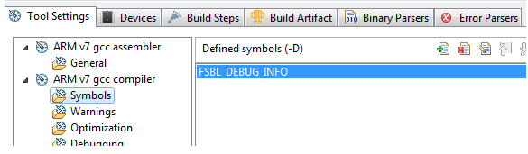
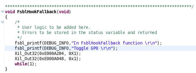
Next, open the fsbl_hooks.c from fsbl/src in the Project Explorer, and add the code to toggle the GPIO that we added in the Hardware. You can add the register writes seen below to the FsblHookFallback function:
Right click on the FSBL, and select Generate Linker Script, and place all sections in ps7_ram_0 and Generate.
Create Microblaze Hello World Application:
Create the MicroBlaze Hello World Application. Select New -> Application Project. Set the Project Name to "hello", and the Processor to "microblaze_0" and select Next. Select the Hello World and Finish. This will automatically create the BSP. The BSP will use the PS7_UART_1 for STDIN/OUT as we have connected the DP interface on the MicroBlaze to the GP port which allows access to PS IP (including the UART). Generate the Linker script for this application and make sure all sections are in the DDR.Note: Both the MicroBlaze app and the FSBL are sharing the same ps7_uart_1. Be aware that if both processors try to write at the same time, you might see issues.
Boot Image Creation:
Here, we will be booting from the SD card. To create a BIN image for the SD card, use the Create Boot Image tool in the SDK. Right click on the FSBL, and select Create Boot Image. The FSBL and the BIT should be pre-populated. If not, then you can add these manually using the Add button in the GUI.Note: the FSBL partition type is bootloader, all other partitions are datafile. Add the hello.elf (select Add, and browse to the hello.elf. The partition type is datafile):

Select Create Image to create the BOOT.BIN file.
Booting from SD Card:
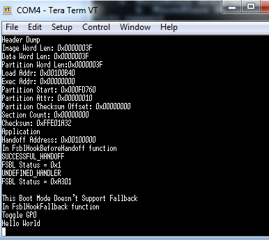
Place this BOOT.bin file onto the SD card, and set the bootmode to boot from the SD card and power on the board. You will see the FSBL debug information, and the Hello World App: