Time-Sensitive Networking (TSN) is a set of standards under development by the Time-Sensitive Networking task group of the IEEE 802.1 working group.
Table of Contents
Xilinx TSN IP Support
- Enhanced Time Synchronization using IEEE 802.1AS
Ethernet AVB (Audio Video Bridging, IEEE 802.1Qav)
- Frame Replication and Elimination for Reliability IEEE 802.1CB
- Enhancements for Scheduled Traffic IEEE 802.1Qbv
- Per-Stream Filtering and Policing, IEEE 802.1 Qci
- Enhancements and Performance Improvements, IEEE 802.1Qcc
- Frame Preemption, IEEE 802.1Qbu
- Interspersing Express Traffic, IEEE 802.3br
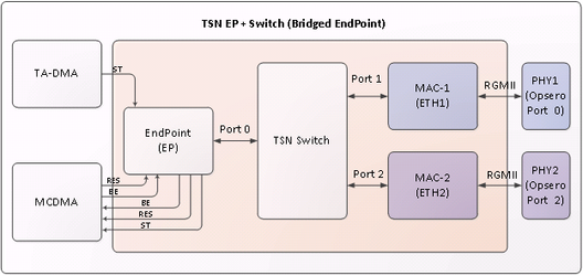
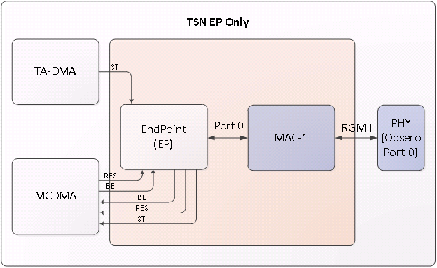
TSN System
- Xilinx’s TSN IP Switch have three ports Endpoint (Port 0), MAC1 (Port 1) and MAC2 (Port 2)
- Endpoint is connected to MCDMA (Multichannel DMA), each MCDMA channel is a dedicated channel for each type of traffic, i.e. Best Effort, Scheduled Traffic and Reserved. There could be other use cases where there would be separate channels for management traffic
- MAC1 is connected to external world by PHY1
- MAC2 is connected to external world by PHY2
Traffic Classes
TSN IP supports two configurations :
a. 3 queue or 3 traffic class system:
1. Best Effort
2. Scheduled
3. Reserved
b. 2 queue/2 traffic class system
1. Best Effort
2. Scheduled
PCP and Traffic Class
The vlan pcp of the ethernet frame is used to identify the traffic class by the HW. By default, pcp of 4 is mapped to ST and pcp’s of 2 and 3 are mapped to RES(reserved). If pcp is any other or if frame has no vlan tag, its considered as BE.
2019.x and earlier releases:
This default mapping can be changed by kernel command line option, in uEnv.txt.
For eg.
bootargs=console=ttyPS0,115200 xilinx_tsn_ep.st_pcp=5 xilinx_tsn_ep.res_pcp=2,3 root=/dev/mmcblk0p2 rw rootwait earlyprintk
2020.x and later releases:
The arguments in boot.scr determine PCP mapping. The default values remain same as mentioned above.
To change the PCP, edit the file <TOP_DIR>/sources/meta-xilinx-tsn/recipes-bsp/u-boot/uboot-zynq-scr/boot.cmd.sd.<boardname>.
For example, the following command line maps a pcp of 1 to ST traffic, a pcp of 4 to RES traffic, and the
rest of the pcps to BE traffic:
bootargs=console=ttyPS0,115200 xilinx_tsn_ep.st_pcp=1 xilinx_tsn_ep.res_pcp=4
root=/dev/mmcblk0p2 rw rootwait earlyprintk
The following command line maps pcps of 2 and 3 to ST traffic, a pcp of 1 to RES traffic, and the rest of the pcps to BE traffic.
bootargs=console=ttyPS0,115200 xilinx_tsn_ep.st_pcp=2,3 xilinx_tsn_ep.res_pcp=1
root=/dev/mmcblk0p2 rw rootwait earlyprintk
After changing the PCP values, source the bitbake environment and run bitbake build again:
#source setupsdk
#bitbake core-image-minimal
CAUTION: Do not edit the boot.scr file directly.
Generating TSN Traffic:
Generating TSN Traffic, can be done by using raw sockets, where you can create ethernet frame with relevant pcp. One such implementation is tsn_talker provided as part of TSN Yocto SW release.
Converting Legacy Applications to TSN
Sometimes users need port legacy applications to send/receive TSN Traffic without having to change/modify them. For example, an application which only uses L3 layer (IP) to communicate shall not have capabilities to insert pcp/vlan into the frame. To solve this, Xilinx TSN Solution has IP interception kernel module support, to seamlessly transition legacy applications to use TSN technology. See "Running IPIC" section for more details.
PTP Profiles Supported
TSN IP has support for following profiles:
a. 1588v1 and 1588v2
b. Power Profile
c. 802.1AS
d. 802.1ASREV
TSN driver and SW daemon (ptp4l and openAvnu/gptp) support is available for :
a. 1588v2
b. 802.1AS
c. 802.1ASREV (not all features may be available. See ptp4l/openAvnu documentation).
PTP offload on R5 in zynqmp
Xilinx TSN solution offers running multiple instances of 802.1AS PTP function(ptp4l) on RPU of zyng Ultrascale platform. This is implemented by porting PTP(ptp4l) daemon and part of TSN IP driver to FreeRTOS running on R5. The control path is handled through A53(main processor), through OpenAMP frame-work.
This enables customers who intend to completely isolate and have a resilient PTP function.
Running gPTP(802.1AS):
gPTP daemon can be run in two ways. One way is to run it from OpenAvnu, and the other is to run it from ptp4linux. Latter is preferred as it prints rms values at slave to identify sync with master.
- Running gPTP daemon from OpenAvnu:
From the Intel card PC machine launch gPTP daemon as follows:
#Open-AVB/daemons/gptp/linux/build/obj/daemon_cl enp4s0 –S
From the Xilinx board launch PTP daemon as follows:
#daemon_cl eth1 –S
[1] 186
ERROR at 636 in ../src/linux_hal_common.cpp: Group ptp not found, will try root (0) instead
Using clock device: /dev/ptp0
Starting PDelay
root@Xilinx-ZCU102-2016_1:~# AsCapable: Enabled
*** Announce Timeout Expired - Becoming Master
New Grandmaster "00:0A:35:FF:FE:00:01:0E" (previous "00:00:00:00:00:00:00:00")
<<END>>
- Running gPTP daemon from ptp4linux:
From the Xilinx board launch PTP daemon as follows:
#ptp4l -P -2 -H -i eth1 -p /dev/ptp0 –s -m -f /usr/sbin/ptp4l_slave.conf
Download PTP daemon from https://sourceforge.net/p/linuxptp/ and compile to get ptp4l binary in Intel card PC. Use gPTP.cfg or default.cfg file present in the linuxptp source code.
From the Intel card PC launch PTP daemon as follows:
(Use /usr/bin/ptp4l_master.conf from the board on PC)
#ptp4l -P -2 -H -i enp4s0 -p /dev/ptp0 -m -f ptp4l_master.conf
Upon successful synchronization, RMS values prints at the slave would be as follows:
root@zcu102-zynqmp:~# ptp4l -P -2 -H -i eth1 /dev/ptp0 -s -m -f /usr/sbin/ptp4l_slave.conf
ptp4l[7940.770]: selected /dev/ptp0 as PTP clock
ptp4l[7940.800]: driver changed our HWTSTAMP options
ptp4l[7940.800]: tx_type 1 not 1
ptp4l[7940.800]: rx_filter 1 not 12
ptp4l[7940.800]: port 1: INITIALIZING to LISTENING on INITIALIZE
ptp4l[7940.800]: port 0: INITIALIZING to LISTENING on INITIALIZE
ptp4l[7948.772]: port 1: LISTENING to MASTER on ANNOUNCE_RECEIPT_TIMEOUT_EXPIRES
ptp4l[7948.772]: selected best master clock 000a35.fffe.00010e
ptp4l[7948.772]: assuming the grand master role
ptp4l[7949.452]: port 1: new foreign master a0369f.fffe.684c96-1
ptp4l[7953.452]: selected best master clock a0369f.fffe.684c96
ptp4l[7953.452]: port 1: MASTER to UNCALIBRATED on RS_SLAVE
ptp4l[7953.951]: port 1: UNCALIBRATED to SLAVE on MASTER_CLOCK_SELECTED
ptp4l[7954.701]: rms 1732 max 2297 freq -100287 +/- 1208 delay 509 +/- 0
ptp4l[7955.701]: rms 326 max 499 freq -101341 +/- 438 delay 509 +/- 0
ptp4l[7956.702]: rms 545 max 579 freq -102323 +/- 151 delay 509 +/- 0
ptp4l[7957.702]: rms 343 max 463 freq -102512 +/- 9 delay 509 +/- 0
ptp4l[7958.702]: rms 118 max 193 freq -102419 +/- 43 delay 509 +/- 0
Note:
- Currently 1 step ptp mode is not supported in software
- The roles of master and slave can be changed by changing the priority values. A low priority implies it is a master and a higher priority implies it is a slave.
By default the MAC ports link speed is 1Gbps, use the following command to set it at 100Mbps, incase 100Mbps setting is required
# mii-tool -F 100baseTx-FD eth1
Change the ptp4l config files (/usr/sbin/ptp4l_slave.conf and /usr/sbin/ptp4l_master.conf) parameter neighborPropDelayThresh as below
neighborPropDelayThresh 2000 - for 100Mbps link speed
or
neighborPropDelayThresh 800 - for 1Gbps link speed
Running PTP 1588v2 :
- PTPv2 uses Best Master Clock algorithm to determine which clock is of highest quality(grand master) within the network to create master/slave hierarchy and synchronizes all other nodes with grand master. To make a node master, priority field in configuration file should have the least value.
- PTPv2 can be run over L2 or UDP. When run over UDP, it can be run in multicast mode on ep + switch systems and in both multicast and unicast modes on ep only systems.
- To Run on Intel Card PC, download PTP daemon from https://sourceforge.net/p/linuxptp/ and compile to get ptp4l binary. Copy master/slave configuration files to linuxptp folder and launch ptp4l daemon from the folder as mentioned below.
To run PTPv2 over L2:
Peer to Peer(P2P) mechanism:
To run as master on zcu102 or zc702:
ptp4l -P -2 -H -i eth1 -p /dev/ptp0 -m -f /usr/sbin/ptp4l_master_v2_l2.conf
To run as slave on zcu102 or zc702:
ptp4l -P -2 -H -i eth1 -p /dev/ptp0 -m -f /usr/sbin/ptp4l_slave_v2_l2.conf
To run as master on Intel Card PC:
ptp4l -P -2 -H -i eth1 -p /dev/ptp0 -m -f ptp4l_master_v2_l2.conf
To run as slave on Intel Card PC:
ptp4l -P -2 -H -i eth1 -p /dev/ptp0 -m -f ptp4l_slave_v2_l2.conf
End to End(E2E) mechanism:
To run as master on zcu102 or zc702:
ptp4l -E -2 -H -i eth1 -p /dev/ptp0 -m -f /usr/sbin/ptp4l_master_v2_l2.conf
To run as slave on zcu102 or zc702:
ptp4l -E -2 -H -i eth1 -p /dev/ptp0 -m -f /usr/sbin/ptp4l_slave_v2_l2.conf
To run as master on Intel Card PC:
ptp4l -E -2 -H -i eth1 -p /dev/ptp0 -m -f ptp4l_master_v2_l2.conf
To run as slave on Intel Card PC:
ptp4l -E -2 -H -i eth1 -p /dev/ptp0 -m -f ptp4l_slave_v2_l2.conf
PTPv2 over UDP and in multicast mode:
Peer to Peer(P2P) mechanism:
To run as master on zcu102 or zc702:
ptp4l -P -4 -H -i eth1 -p /dev/ptp0 -m -f /usr/sbin/ptp4l_master_v2_udp_multicast.conf
To run as slave on zcu102 or zc702:
ptp4l -P -4 -H -i eth1 -p /dev/ptp0 -m -f /usr/sbin/ptp4l_slave_v2_udp_multicast.conf
To run as master on Intel Card PC:
ptp4l -P -4 -H -i eth1 -p /dev/ptp0 -m -f ptp4l_master_v2_udp_multicast.conf
To run as slave on Intel Card PC:
ptp4l -P -4 -H -i eth1 -p /dev/ptp0 -m -f ptp4l_slave_v2_udp_multicast.conf
End to End(E2E) mechanism:
To run as master on zcu102 or zc702:
ptp4l -E -4 -H -i eth1 -p /dev/ptp0 -m -f /usr/sbin/ptp4l_master_v2_udp_multicast.conf
To run as slave on zcu102 or zc702:
ptp4l -E -4 -H -i eth1 -p /dev/ptp0 -m -f /usr/sbin/ptp4l_slave_v2_udp_multicast.conf
To run as master on Intel Card PC:
ptp4l -E -4 -H -i eth1 -p /dev/ptp0 -m -f ptp4l_master_v2_udp_multicast.conf
To run as slave on Intel Card PC:
ptp4l -E -4 -H -i eth1 -p /dev/ptp0 -m -f ptp4l_slave_v2_udp_multicast.conf
PTPv2 over UDP and in unicast mode:
Peer to Peer(P2P) mechanism:
To run as master on zcu102 or zc702:
ptp4l -P -4 -H -i eth1 -p /dev/ptp0 -m -f /usr/sbin/ptp4l_master_v2_udp_unicast_p2p.conf
To run as slave on zcu102 or zc702:
'peer_address' field of /usr/sbin/ptp4l_slave_v2_udp_unicast_p2p.conf should be set to the
IP address of master
ptp4l -P -4 -H -i eth1 -p /dev/ptp0 -m -f /usr/sbin/ptp4l_slave_v2_udp_unicast_p2p.conf
To run as master on Intel Card PC:
ptp4l -P -4 -H -i eth1 -p /dev/ptp0 -m -f ptp4l_master_v2_udp_unicast_p2p.conf
To run as slave on Intel Card PC:
'peer_address' field of ptp4l_slave_v2_udp_unicast_p2p.conf should be set to the
IP address of master
ptp4l -P -4 -H -i eth1 -p /dev/ptp0 -m -f ptp4l_slave_v2_udp_unicast_p2p.conf
End to End(E2E) mechanism:
To run as master on zcu102 or zc702:
ptp4l -E -4 -H -i eth1 -p /dev/ptp0 -m -f /usr/sbin/ptp4l_master_v2_udp_unicast_e2e.conf
To run as slave on zcu102 or zc702:
'UDPv4' field of /usr/sbin/ptp4l_slave_v2_udp_unicast_e2e.conf should be set to the
IP address of master
ptp4l -E -4 -H -i eth1 -p /dev/ptp0 -m -f /usr/sbin/ptp4l_slave_v2_udp_unicast_e2e.conf
To run as master on Intel Card PC:
ptp4l -E -4 -H -i eth1 -p /dev/ptp0 -m -f ptp4l_master_v2_udp_unicast_e2e.conf
To run as slave on Intel Card PC:
'UDPv4' field of ptp4l_slave_v2_udp_unicast_e2e.conf should be set to the
IP address of master
ptp4l -E -4 -H -i eth1 -p /dev/ptp0 -m -f ptp4l_slave_v2_udp_unicast_e2e.conf
On successful synchronization, logs at the slave would be as follows:
ptp4l[765.873]: selected /dev/ptp0 as PTP clock
ptp4l[765.960]: driver rejected most general HWTSTAMP filter
ptp4l[765.960]: port 1: INITIALIZING to LISTENING on INIT_COMPLETE
ptp4l[765.960]: port 0: INITIALIZING to LISTENING on INIT_COMPLETE
ptp4l[772.710]: port 1: LISTENING to MASTER on ANNOUNCE_RECEIPT_TIMEOUT_EXPIRES
ptp4l[772.710]: selected local clock 000a35.fffe.00012e as best master
ptp4l[772.710]: assuming the grand master role
ptp4l[775.065]: port 1: new foreign master 000a35.fffe.00013e-1
ptp4l[779.065]: selected best master clock 000a35.fffe.00013e
ptp4l[779.065]: port 1: MASTER to UNCALIBRATED on RS_SLAVE
ptp4l[780.064]: master offset 3409342692 s0 freq +0 path delay 396
ptp4l[781.065]: master offset 3409344460 s1 freq +1768 path delay 396
ptp4l[782.065]: master offset -373 s2 freq +1395 path delay 396
ptp4l[782.065]: port 1: UNCALIBRATED to SLAVE on MASTER_CLOCK_SELECTED
ptp4l[783.065]: master offset -333 s2 freq +1323 path delay 396
ptp4l[784.065]: master offset -404 s2 freq +1152 path delay 396
ptp4l[785.065]: master offset -381 s2 freq +1054 path delay 396
ptp4l[786.065]: master offset -303 s2 freq +1017 path delay 396
ptp4l[787.065]: master offset -297 s2 freq +933 path delay 396
ptp4l[788.065]: master offset -19 s2 freq +1121 path delay 396
ptp4l[789.065]: master offset 316 s2 freq +1451 path delay 396
ptp4l[790.065]: master offset 373 s2 freq +1603 path delay 396
The s0, s1, s2 strings indicate the different clock servo states: s0 is unlocked, s1 is clock step and s2 is locked. Once the servo is in the locked state, the clock will not be stepped (only slowly adjusted). INITIALIZING, LISTENING, UNCALIBRATED and SLAVE are some of possible port states which change on the INITIALIZE, RS_SLAVE, MASTER_CLOCK_SELECTED events. The master offset value is the measured offset from the master in nanoseconds. This has decreased from 3409342692 to -373 indicating successful synchronization with master changing the port state from UNCALIBRATED to SLAVE.
Running Qbv/Time Aware Shaper:
Qbv functionality can be programmed using qbv_sched utility.
For Example:
qbv_sched -c ep /tmp/abc.cfg
This schedules Qbv on ep using the TSN configuration of abc.cfg present in tmp directory
qbv_sched ep
This schedules Qbv on ep using the default TSN configuration present in /etc/qbv.cfg
qbv_sched -g ep
This returns the schedule running on ep
qbv_sched -s ep -f
This forces a Qbv schedule on ep even if a schedule is pending to be run on ep
qbv_sched -c ep /tmp/abc.cfg -f
This forcefully runs Qbv using TSN configuration of abv.cfg presnt in tmp directory even if a schedule is pending to be run on ep
Testing with Wireshark:
Configuring Qbv:
The default TSN configuration is present in the /etc/qbv.cfg file. This file has the QBV gate schedule. To run Qbv, you need to configure this file as per the instructions given in it. To open all gates, cycle_time should be 0.
For Example:
qbv =
{
              temac1 =
              {
                      start_sec = 0;
                      start_ns = 0;
                      cycle_time = 10000000; //cycle time is 10ms
                      gate_list_length = 2;
                      gate_list =
                          (
                             {
                                  state = 4;
                                  time = 100000;
                             },
                             {
                                    state = 1;
                                    time = 100000;
                              }

                          );
               };
};
As 'temac1' part of the file is configured, Qbv scheduler is run on 'eth1' using qbv_sched utility as follows:
# qbv_sched eth1
qbv_sched utility can be used to schedule all interfaces ep, eth1- temac1 and eth2- temac2
The above Qbv schedule opens ST gate for 100uS and then closes it. Cycle time is 10ms; So after 100uS BE gate is kept open for the rest of the cycle time even though it's gate time is 100uS as the sum of gate time's is not cycle time.
To test TSN functionality you need to run PTP in the background and make sure it’s working without any errors. After PTP starts running in the background, run tsn_talker program from the Xilinx HW. Before launching tsn_talker application configure the switch CAM entry to allow corresponding traffic.
#switch_cam -a a0:36:9f:68:4c:96 10 swp1
Switch CAM entry is added with destination MAC as a0:36:9f:68:4c:96, VLAN ID as 10 and port as swp1 (Temac1).
#tsn_talker eth1 a0:36:9f:68:4c:96 00:0a:35:00:01:0e 10 4 1500 0 12 1000000000 1
This application sends 12 ST packets with VLAN ID as 10 and packet size as 1500 bytes every 1 second.
From the Intel card PC, run Wireshark and observe the incoming packets.
Wireshark Before Qbv Programming:
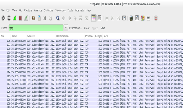
as we can see in the above picture, from 106th packet untill 117th packet are all in sequence and the next packet starts at the next second.
Wireshark After qbv programming:
You would observe that every second 12 ST packets are sent of which 8 packets are sent in the 100us of 10 ms cycle and the rest 4 packets are sent in the next cycle.
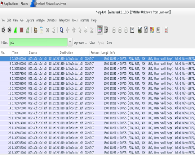
As we can see in the above picture, from 4th packet until 11th packet (8 packets) are received sequentially and the next packet starts after 10ms delay (packet no. 12).
Running IPIC:
IP interception translates the transmit packet with the configured source, destination MAC addresses, VLAN ID and PCP values if the packets' IPv4 tuples (source IP, destination IP, DSCP, protocol, source port number and destination port number) match. IPIC module maintains hash entries of IPv4 tuples and if the out-going packets' tuple data match with that of hash entries , translates the IP stream.
To configure the matching condition of IPv4 tuple, at driver load time, choose '1'(set) or '0' (unset) against the corresponding tuple data where IPv4 tuple order is 'IPv4_tuple=src_ip, dest_ip, dscp, protocol, src_port, dest_port'.
For example, to filter packets that have a specific source IP, source port number, and destination port number, it is needed to load IPIC module as follows:
- insmod /lib/modules/4.14.0-xilinx-v2018.1/extra/xilinx_tsn_ip_intercept.ko IPv4_tuple=1,1,0,0,0,0
In this case, DSCP, protocol, source port number and destination port number are not considered.
User application ipic_prog programs IPIC module to add hash entries corresponding the set IPv4 tuple data, and translate IP stream with provided source, destination MAC addresses, VLAN ID and PCP values when the set IPv4 tuple data matches.
Usage of ipic_prog is as follows:
- ipic_prog <add | del | flush> <src_ip> <dest_ip> <protocol> <dscp> <src_port> <dest_port> <src_mac> <dest_mac> <vlanid> <pcp>
Following are the examples of addition of a single entry, and deletion of single and all entries.
Addition of Entry:
- ipic_prog add 192.168.10.5 192.168.10.9 17 0 8000 1000 00-0a-35-00-01-0e a0-36-9f-68-4c-96 10 4
Deletion of Entry:
- ipic_prog del 192.168.10.5 192.168.10.9 17 0 8000 1000 00-0a-35-00-01-0e a0-36-9f-68-4c-96 10 4
Deletion/Flushing of All Entries:
- ipic_prog flush
If you want to add multiple entries with different IPv4 tuple combinations and different translation fields, run ipic_prog command for each entry.
For example, the following commands add two entries with same source IP and different destination IPs, and translate the streams with different source, destination MAC addresses and VLAN IDs
- ipic_prog add 192.168.10.5 192.168.10.9 17 0 8000 1000 00-0a-35-00-01-0e a0-36-9f-68-4c-96 10 4
In this case, packets with destination IP as 192.168.10.9 are translated with VLAN ID of 10 and MAC address of source as 00:0a:35:00:01:0e and of destination as a0:36:9f:68:4c:96
- ipic_prog add 192.168.10.5 192.168.10.3 17 0 8000 1000 00-0a-35-07-89-ff a0-36-9f-87-44-00 99 4
In this case, packets with destination IP as 192.168.10.3 are translated with VLAN-ID of 99 and MAC addresses of source as 00:0a:35:07:89:ff and of destination as a0:36:9f:87:44:00
the translated IP stream is sent out of network ports if there is a switch CAM entry corresponding to the destination MAC address and VLAN ID. Hence, make sure to add CAM entries using switch_cam command.
For example, for the above two added entries, switch_cam is run as follows:
- switch_cam -a a0:36:9f:68:4c:96 10 swp1
- switch_cam -a a0:36:9f:68:4c:96 99 swp1
Transmit packets from the board, for example, using iperf3 as follows:
- iperf3 -c 192.168.11.9
- iperf3 -c 192.168.11.3
Make sure iperf3 server is run at the receiver as below and observe the received packets with destination MAC, source MAC addresses and VLAN ID.
- iperf3 -s
Running openlldp:
When the system has preemption capabilities, openlldp is run to detect frame preemption capabilities of the peer and if the peer has the capabilities, to enable the preemption.
Run openlldp as follows:
- ‘lldpd’ fields of ‘EXTRA_IMAGEDEPENDS’ and ‘IMAGE_INSTALL_append’ in conf/local.conf (given you are in ‘Yocto_TSN/build’ path) have to be replaced with ‘lldpad’ as follows:
EXTRA_IMAGEDEPENDS += "gptp misc-utils linuxptp bridge-utils python python-json python-codecs python-io curl lldpad strace lrzsz net-tools tcpdump netcat iperf3 iproute2 python-mmap python-flask python-ctypes python-re python-werkzeug python-jinja2 python-itsdangerous gui-init gui-scripts"
IMAGE_INSTALL_append = "gptp misc-utils linuxptp bridge-utils python python-json python-codecs python-io curl lldpad strace lrzsz net-tools tcpdump netcat iperf3 ipic-module iproute2 python-mmap python-flask python-ctypes python-re python-werkzeug python-jinja2 python-itsdangerous gui-init gui-scripts"
- Build the images using ‘bitbake core_image_minimal’
- After boot up, run the following commands:
# lldpad -d
# lldptool set-lldp -i eth1 adminStatus=rxtx
- To add additional ethernet capabilities TLV to openlldp frame, run:
# lldptool -i eth1 set-tlv -V addEth enableTx=yes
Running this command is mandatory for preemption
- To add MAC/PHY configuration status TLV to openlldp frame, run:
# lldptool -i eth1 set-tlv -V macPhyCfg enableTx=yes
- To add Power via MDI TLV to openlldp frame, run:
# lldptool -i eth1 set-tlv -V powerMdi enableTx=yes
- To add link aggregation TLV to openlldp frame, run:
# lldptool -i eth1 set-tlv -V linkAgg enableTx=yes
- To add maximum frame size TLV to openlldp frame, run:
# lldptool -i eth1 set-tlv -V MTU enableTx=yes
- To add system name to openlldp frame, run:
# lldptool -T -i eth1 -V sysName enableTx=yes
- To add port description to openlldp frame, run:
# lldptool -T -i eth1 -V portDesc enableTx=yes
- To add system description to openlldp frame, run:
# lldptool -T -i eth1 -V sysDesc enableTx=yes
- To add system capabilities to openlldp frame, run:
# lldptool -T -i eth1 -V sysCap enableTx=yes
- To add management address to openlldp frame, run:
#lldptool -T -i eth1 -V mngAddr -c ipv4=<ip address(ex:10.0.0.10)>
#lldptool -T -i eth1 -V mngAddr enableTx=yes
For Example:
Steps to Test:
To activate preemption on zcu102 boards with preemption support, connect eth1 of one board to eth1 of the other. Run lldpad daemon on both as follows:
# lldpad -d
# lldptool set-lldp -i eth1 adminStatus=rxtx
Observe if preemption is enabled and active by reading preemption enable register and preemption control status register as follows:
#devmem 0x80040440
#devmem 0x80040444
It is seen that preemption is not enabled and active, and the moment additional Ethernet capabilities TLV is set to be included in the frame in both the boards as follows:
#lldptool -i eth1 set-tlv -V addEth enableTx=yes
It would be seen that lldpad daemon detects the preemption capabilities of the peer and enables preemption in its system if preemption is supported eventually activating the preemption.
Test Results:
Before setting additional Ethernet capabilities TLV:
root@zcu102-zynqmp:~# devmem 0x80040440
0x00000000
root@zcu102-zynqmp:~# devmem 0x80040444
0x00000900
0th bit of preemption enable register is 0 implying preemption is not enabled, and 31st bit of preemption control status register is 0 implying preemption is not active.
After setting additional Ethernet capabilities TLV in both the boards:
root@zcu102-zynqmp:~# devmem 0x80040440
0x00000001
root@zcu102-zynqmp:~# devmem 0x80040444
0x820000900
0th bit of preemption enable register is 1 implying preemption is enabled, and 31st bit of preemption control status register is 1 implying preemption is active.
Running Spanning Tree Protocol
On EP+Switch system running STP using standard linux based tools has been enabled. To enable the HW uses source MAC based filtering mechanism to identify which port a STP frame shall exit from. The TSN driver sets up these filters during driver initialization time. But to make this work, each node of the ring shall have unique mac address set up in device tree during compile time.
To run STP at each node do:
#ip link add name br0 type bridge
#ip link set dev eth1 master br0
#ip link set dev eth2 master br0
#ifconfig br0 up
#ip link set dev br0 type bridge stp_state 1
Check the status of spanning tree
#brctl showstp br0
Time Aware DMA (TADMA)
TimeAware DMA is a feature where users can control the precise time a packet gets picked up for transmission. Not to be confused with time aware shaper (TAS). For example, for a Qbv schedule with cycle time of 1ms, one can program a stream to be triggered at a particular offset. If during that offset the stream’s traffic class window is open the frame is transmitted precisely at that offset.
TADMA is programmed with tadma_prog command, add the streams and trigger point of each stream in the /etc/stream.cfg. Trigger point is relative to qbv cycle start time and it not absolute PTP time.
#tadma_prog -c <interface> <streams config file>
Stream is the combination of MAC address and VLAN ID. TADMA works only for ST – Scheduled Traffic packets. Provide the trigger point for streams on the QBV cycle time and also mention number of pacects to be sent in the count value 1 to 4. Schedule QBV before programming TADMA.
By default TADMA engine works in continuous mode, it fetches ST frames in continuous loop. When streams are programmed it goes into discrete mode fetching frames at trigger point(s).
Example /etc/stream.cfg:
streams =
(
{
dest = "00:0a:35:00:01:0e";
vid = 10;
trigger = 100000;
count = 1; // fetch 1 frame at this time
},
{
dest = "00:0a:35:00:01:0f";
vid = 20;
trigger = 200000;
count = 2; // fetch 2 frame at this time
}
);
OOB Scripts
From 2020.1 lounge release, out of box scripts are included for a basic demonstration of any of the clauses. These scripts can be run directly after linux probe without any additional commands.
OOB scripts are available for:
- Qbv+TADMA
- FRER
- Qci
How to Run
- Boot Linux as usual and find the scripts in / usr sbin / folder of rootfs
- For Qbv and tadma
- the scripts need the destination mac address as an argument. On the link partner, to see the mac address, use the following command:
ifconfig <interface> - run the script for the clause you want to run
- the scripts need the destination mac address as an argument. On the link partner, to see the mac address, use the following command:
#sh qbv_auto.sh <dest mac>
- For FRER and Qci, receiver side script should be run first.
Receiver side
#sh <clause>_receive.sh
Sender side
#sh <clause>_sender.sh
For more details on setup, please refer to Getting Started Guide.
Frequently Asked Questions (FAQs)
Qbv doesn't work - After programming qbv using qbv_sched utility, packets belonging to ST don't come through at specified window.
Answer:
a. Make sure you run PTP first. Without running PTP qbv state machine will stall.
b. Make sure you program the switch CAM for the destination MAC and VLAN associated with traffic you are trying to send.
PTP Clock always starts with Jan 1 1970. This is causing our CNC to misbehave.
By default the PTP RTC clock starts with (0 sec, 0nsec) or Jan 1 1970 at boot up. This can be changed by setting PTP RTC clock to CLOCK_REALTIME of the system clock.
#phc2sys -c /dev/ptp0 -s CLOCK_REALTIME -O 0
Run this command once so the PTP RTC clock gets set with system time(CLOCK_REALTIME).
Qbv behavior is different from ep and temac1/temac2 instances on EP+Switch design
There is slight difference in the Qbv on temac1 and EP egress. The reason is due to EP side its store and forward. On MAC side(temac1 or temac2) if its store and forward(configurable) then they both behave exactly same. If its cut-through which is the case in the reference HW design we release then it behaves slightly different. For example, to send a 1500bytes frame 16uS window would be needed on EP side and slightly higher 16.5uS window needed on temac1+cut_through as cut-through will have some latency on top of 16us.
tsn_talker doesnt run correctly on eth1 or eth2 on EP+Switch design
Starting from 2018.3, the data path is moved to internal cpu bounded interface "ep". On network ports eth1 and eth2 only control path(STP/LLDP/PTP) frames can be transmitted or received. Please use tsn_talker with ep interface.
tsn_talker transmits garbled frames
This is expected and intentional. TSN talker is programmed such a way to send arbitrary IPv6 frame with payload having random data. It however has sequence number at fixed offset in the payload to identify and/or figure out say how Qbv is working.
Compiling TSN drivers outside of TSN Yocto release
The TSN drivers and subsystem package(Yocto version) is delivered to our licensed customers via TSN lounge Access on Xilinx.com. Although the TSN drivers are available on xilinx kernel https://github.com/Xilinx/linux-xlnx, they may not be the latest. As we streamline driver delivery with our Yocto release available against Vivado release, its always recommended to use Lounge release. Eventually all TSN drivers will be pushed to Xilinx github kernel also the device tree infrastructure will be pushed to https://github.com/Xilinx/device-tree-xlnx.
PTP on slave looses sync with master, when master reboots
Run ptp4l with slave and master. After a while reboot the master system and run ptp4l again. Now ptp4l instance on the slave never regains the sync with master and post huge rms :
ptp4l[1471.104] rms 1257113383298 max 1257507158007 freq +90000000 +/- 0 delay 407 +/- 0
ptp4l[1471.104] rms 1257103383298 max 1257506158007 freq +90000000 +/- 0 delay 407 +/- 0
Answer:
From the ptp4l man page:
step_threshold
The maximum offset the servo will correct by changing the clock frequency instead of stepping the clock. When set to 0.0, the servo will never step the clock except on start. It's specified in seconds. The default is 0.0.
So the clock is only adjusted at start of daemon and not during the running of the daemon. You can by pass this by setting step_threshold in ptp4l_slave.cfg to say 1ms
/* add this line to ptp4l cfg file on slave */
step_threshold 0.001
This will force the daemon to step the clock if difference between master and slave is more than 1ms. It is usually not recommended as the stepping the clock would dramatically change the time for all the running applications using the ptp time.
How to run PTP Boundary Clock on EP+Switch design
When EP+Switch design is instantiated, the system shall have two network interfaces(eth1 and eth2) and one internal cpu port/interface(ep). PTP daemon can be run independently on eth1 or eth2 when using the system as end node. But when this system becomes part of TSN network where both eth1 and eth2 are connected to external systems, it is important to run PTP daemon (single instance) on both the interfaces(eth1, eth2). There is only one PTP hardware clock (RTC) in the system.
To run BC using ptp4l:
Enable clock_type field in ptp4l config file as BC. Then run ptp4l as follows. The BMCA shall happen across the device. If the Xilinx device becomes GM (through BMCA) then devices connected through eth1 as well as eth2 shall sync their clock(slave) with its PTP clock.
#ptp4l -P -2 -H -i eth1 -i eth2 -p /dev/ptp0 -m -f /usr/sbin/ptp4l.conf
ptp4l[139.040]: selected /dev/ptp0 as PTP clock
ptp4l[139.076]: driver rejected most general HWTSTAMP filter
ptp4l[139.076]: port 1: INITIALIZING to LISTENING on INIT_COMPLETE
ptp4l[139.108]: driver rejected most general HWTSTAMP filter
ptp4l[139.108]: port 2: INITIALIZING to LISTENING on INIT_COMPLETE
ptp4l[139.108]: port 0: INITIALIZING to LISTENING on INIT_COMPLETE
ptp4l[142.111]: port 2: new foreign master 000a35.fffe.00012e-1
ptp4l[146.111]: selected best master clock 000a35.fffe.00012e
ptp4l[146.112]: port 2: LISTENING to UNCALIBRATED on RS_SLAVE
ptp4l[146.780]: port 1: LISTENING to MASTER on ANNOUNCE_RECEIPT_TIMEOUT_EXPIRES
ptp4l[146.780]: selected best master clock 000a35.fffe.00012e
ptp4l[147.362]: port 2: UNCALIBRATED to SLAVE on MASTER_CLOCK_SELECTED
ptp4l[147.987]: rms 3090228936610 max 6180457873230 freq -160 +/- 65 delay 394 +/- 0
ptp4l[148.987]: rms 39 max 49 freq -240 +/- 8 delay 392 +/- 0
ptp4l[149.971]: port 1: new foreign master a0369f.fffe.684c96-1
ptp4l[149.987]: rms 18 max 25 freq -239 +/- 7 delay 392 +/- 0
ptp4l[150.988]: rms 8 max 13 freq -233 +/- 10 delay 393 +/- 0
ptp4l[151.988]: rms 8 max 14 freq -239 +/- 8 delay 393 +/- 0
TADMA + Qbv doesn't work - After programming tadma using tadma_prog and qbv using qbv_sched utility, packets belonging to ST don't come through at specified window.
Answer:
a. Make sure you run PTP first. Without running PTP qbv state machine will stall.
b. Make sure you have a valid schedule on EP Qbv.
c. Make sure your cycle time is greater than all trigger points.
d. Make sure your ST traffic is matching with the streams programmed in streams.cfg
Points to note
TADMA is always programmed with ep qbv instance in discrete mode.
It depends only on cycle time and it should be greater than last stream’s trigger time in tadma config (streams.cfg).
It should have a valid ST window within the cycle. (at least one packet to go out)
The current TSN design uses all the 16 PL-PS interrupts(IRQ0 and IRQ1) available on the PS (Zynq Ultrascale+) . We have some other PL modules which have interrupts that need to be connected to the PS.
Answer: See TSN Design with AXI Interrupt Controller
- How to create rootfs on SD cardNOTE: unenv.txt is not used in 2020.x and later releases. Please refer to TSN SW user guide for more details. See PCP section above on how to specify PCP values without uenv file.
- Take fitImage-<board name>.bin, BOOT-<board name>.bin, uEnv.txt(only until 2019.x release), boot.scr and core-image-minimal-<board name>.cpio from tmp/deploy/images/<board name>/ . Rename BOOT-<board name>.bin to BOOT.bin.
- Replace “fit_image=fitImage-core-image-minimal-<board name>-<board name>” with “fit_image=fitImage-<board name>.bin” in uEnv.txt (only until 2019.x release)
- Using GParted Partition Editor or fdisk command line argument, partition SD card into two parts. First part must have FAT32 file system and it’s size should be a little more than the size of fitImage-<board name>.bin, BOOT.bin, uEnv.txt(only until 2019.x release) and boot.scr combined.
- The second part would contain the remaining portion of SD card and it must have EXT3 file system.
- Copy fitImage-<boardname>.bin, BOOT.bin, uEnv.txt(only until 2019.x release) and boot.scr to the first partition (the one with FAT32 file system)
- Go to the mount area of second partition and run “cpio -iv < <location of core-image-minimal-<board name>.cpio>” (For example: “cpio -iv < /media/core-image-minimal-<board name>.cpio”)
- Boot the board with SD card. When you change any file such as /etc/qbv.cfg, changes would be retained on reboot.
TSN Design with AXI Interrupt Controller
AXI Interrupt Controller can be connected in cascade mode on Zynq and ZynqMP platforms i.e. PL-interruptpin--->AXI-INTC-→GIC. In this case, the peripherals using AXI-INTC as interrupt controller, will register their handlers to AXI-INTC and they can generate interrupts to AXI-INTC. AXI-INTC be will registered as peripheral to GIC. Whenever peripheral generates interrupts to AXI-INTC, then it generates interrupts to GIC.
Usage
AXI Interrupt Controller will be very useful when the system required more than 16 interrupt lines to connect to Zynq/ZynqMP.
The following figure shows how interrupts are concatenated and connected to axi_intc which is cascaded to ZynqMP pl_ps_irq0.
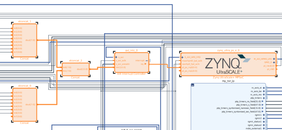
Figure : Connecting peripheral interrupt lines to axi_intc
Device Tree Generation Issue
For the proper generation of the device tree, the following setting is needed in axi_intc IP.
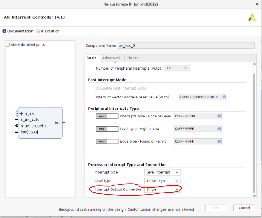
Figure : Changing irq output connection for proper dtg
This setting enables irq pin and ensures proper generation of interrupt-parent and interrupt numbers within axi_intc node.
|
Known issues and troubleshooting
→ Repeated ping on broadcast packets can be observed when TSN boards are connected in a a loop configuration. This can be observed with 2 back to back boards or more where is a possibility of a loop in the network. A standard solution for this is STP enabled (see below). This is NOT specific to TSN systems and it is common precaution for any network with possible loops.
ip link add name br0 type bridge
ip link set dev eth1 master br0
ip link set dev eth2 master br0
ifconfig br0 up
ip link set dev br0 type bridge stp_state 1
→ Under heavy traffic PTP can go out of sync with TIMEOUT errors indicating that PTP process and underlying timestamp fetch did not receive enough time/priority to run. Tuning this depends on the traffic in the system but the typicall recommendations are below:
- Increase tx_timestamp_timeout to 10 in PTP config file. If using a board to board setup, this can be updated on both master and slave config to account for increased TX and RX traffic.
- If using tsn_talker to send traffic, no more than 3 instances of tsn talker can be used at full throughput with packet size of 1472.