This page provides detailed information related to Design Module 2 - SDI Video Capture and Display with PLDDR
Table of Contents
1 Overview
The primary goal of this Design is to demonstrate the capabilities of VCU hard block present in Zynq UltraScale+ EV devices. The TRD will serve as a platform to tune the performance parameters of VCU and arrive at optimal configurations for encoder and decoder blocks.
This design supports the following video interfaces:
Sources:
SDI-Rx capture pipeline implemented in the PL.
File source (SD card, USB storage, SATA hard disk).
Stream-In from network or internet.
Sinks:
DP-Tx display pipeline in the PS.
SDI-Tx display pipeline implemented in the PL.
VCU Codec:
Video Encode/Decode capability using VCU hard block in PL
AVC/HEVC encoding.
Encoder/decoder parameter configuration.
Streaming Interfaces:
1G Ethernet PS GEM
Video format:
XV20
Audio Configuration:
Codec: AAC
Format: S24_32LE
Channel: 2
Sampling rate: 48 kHz
Supported Resolution
The table below provides the supported resolution from GUI and command-line app in this design.
Resolution | GUI | Command Line |
Single Stream | Single Stream | |
4Kp60 | X | √ |
4Kp30 | X | √ |
1080p60 | X | √ |
√ - Supported
x – Not supported
The below table gives information about the features supported in this design.
Pipeline | Input Source | Output Type | ALSA Srivers | Resolution | Audio Codec Type | Audio Configuration | Video Codec | Deliverables |
|---|---|---|---|---|---|---|---|---|
Record/Stream-Out pipeline | SDI-Rx | File Sink/ Stream-Out | SDI-Rx ALSA drivers | 4K/1080p | AAC | 2 channel @ 48 kHz | HEVC/AVC | SDI-Rx Audio encode with soft codec and video with VCU and store it in a container format. |
Playback pipeline | File Source/ Stream-In | SDI-Tx | SDI-Tx ALSA drivers | 4K/1080p | AAC | 2 channel @ 48 kHz | HEVC/AVC | Playback of the local-file/stream-in with video decoded using VCU and Audio using GStreamer soft codec. |
Capture → Display | SDI-Rx | SDI-Tx | SDI-Rx ALSA drivers and SDI-Tx ALSA drivers | 4K/1080p | NA | 2 channel @ 48 kHz | HEVC/AVC | SDI-Rx Audio /Video pass to SDI-Tx without VCU/Audio-Codec. |
Capture → Encode → Decode → Display | SDI-Rx | SDI-Tx | SDI-Rx ALSA drivers and SDI-Tx ALSA drivers | 4K/1080p | NA | 2 channel @ 48 kHz | HEVC/AVC | SDI-Rx raw audio and video with VCU encoder and decode to achieve AV sync. |
The below figure shows the SDI Video Capture and SDI Display with Audio design hardware block diagram.

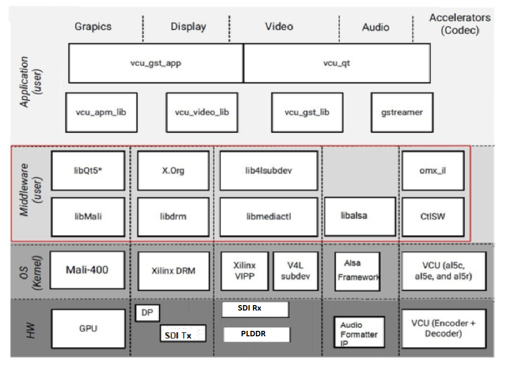
The below figure shows the SDI Video Capture and SDI Display with Audio design software block diagram.
1.1 Board Setup
Refer below link for board setup
1.2 Run Flow
The TRD package is released with the source code, Vivado project, Petalinux BSP, and SD card image that enables the user to run the demonstration. It also includes the binaries necessary to configure and boot the ZCU106 board. Prior to running the steps mentioned in this wiki page, download the TRD package and extract its contents to a directory referred to as TRD_HOME which is the home directory.
Refer below link to download all TRD contents.
Refer Section 4.1 : Download the TRD of
Zynq UltraScale+ MPSoC VCU TRD 2020.1wiki page to download all TRD contents.
TRD package contents specific to SDI Video Capture and SDI Display with Audio design are placed in the following directory structure. The user needs to copy all the files from the $TRD_HOME/images/vcu_sdi_xv20 to FAT32 formatted SD card directory.
rdf0428-zcu106-vcu-trd-2020-1
├── apu
│   └── vcu_petalinux_bsp
├── images
│   ├── vcu_10g
│   ├── vcu_audio
│   ├── vcu_hdmi_multistream_xv20
│   ├── vcu_hdmi_rx
│   ├── vcu_hdmi_tx
│   ├── vcu_llp2_hdmi_nv12
│   ├── vcu_llp2_hdmi_nv16
│   ├── vcu_llp2_hdmi_xv20
│   ├── vcu_llp2_sdi_xv20
│   ├── vcu_multistream_nv12
│   ├── vcu_pcie
│   ├── vcu_sdirx
│   ├── vcu_sditx
│   └── vcu_sdi_xv20
├── pcie_host_package
│   ├── COPYING
│   ├── include
│   ├── libxdma
│   ├── LICENSE
│   ├── readme.txt
│   ├── RELEASE
│   ├── tests
│   ├── tools
│   └── xdma
├── pl
│   ├── constrs
│   ├── designs
│   ├── prebuild
│   ├── README.md
│   └── srcs
└── README.txt
TRD package contents specific to SDI Video Capture and SDI Display PLDDR design are placed in the following directory structure.
rdf0428-zcu106-vcu-trd-2020-1
├── apu
│   └── vcu_petalinux_bsp
│       └── xilinx-vcu-zcu106-v2020.1-final.bsp
├─images
│   └── vcu_sdi_xv20
│       ├── autostart.sh
│       ├── BOOT.BIN
│       ├── boot.scr
│       ├── config
│       ├── image.ub
│       ├── system.dtb
│       └── vcu
├── pcie_host_package
├── pl
│   ├── constrs
│   ├── designs
│   │   ├── zcu106_picxo_plddr_sdi
│   ├── prebuild
│   │   ├── zcu106_picxo_plddr_sdi
│   ├── README.md
│   └── srcs
│       ├── hdl
│       └── ip
└── README.txt
Configuration files (input.cfg) for various Resolutions are placed in the following directory structure in /media/card.
config
├── 1080p60
│   ├── Display
│   ├── Record
│   ├── Stream-in
│   └── Stream-out
├── 4kp30
│   ├── Display
│   ├── Record
│   ├── Stream-in
│   └── Stream-out
└── 4kp60
│   ├── Display
│   ├── Record
│   ├── Stream-in
│   └── Stream-out
└── input.cfg
1.2.1 GStreamer Application (vcu_gst_app)
The vcu_gst_app is a command-line multi-threaded Linux application. The command-line application requires an input configuration file (input.cfg) to be provided in the plain text.
Execution of the application is shown below:
$ vcu_gst_app < path to *.cfg file>
Example:
4kp60 HEVC_HIGH Display Pipeline execution
$ vcu_gst_app /media/card/config/4kp60/Display/Single_4kp60_HEVC_HIGH.cfg
4kp60 HEVC_HIGH Record Pipeline execution
$ vcu_gst_app /media/card/config/4kp60/Record/Single_4kp60_HEVC_HIGH.cfg
4kp60 HEVC_HIGH Stream-out Pipeline execution
$ vcu_gst_app /media/card/config/4kp60/Stream-out/Single_4kp60_HEVC_HIGH.cfg
4kp60 HEVC_HIGH Stream-in Pipeline execution
$ vcu_gst_app /media/card/config/4kp60/Stream-in/input.cfg
Make sure SDI-Rx should be configured to 4kp60 mode.
To measure the latency of the pipeline, run the below command. The latency data is huge, so dump it to a file.
$ GST_DEBUG="GST_TRACER:7" GST_TRACERS="latency" GST_DEBUG_FILE=/run/latency.log vcu_gst_app /media/card/config/input.cfg
Refer below link for detailed run flow steps
1.3 Build Flow
Refer below link for build flow
2 Other Information
2.1 Known Issues
For Petalinux related known issues please refer: PetaLinux 2020.1 - Product Update Release Notes and Known Issues
For VCU related known issues please refer AR# 66763: LogiCORE H.264/H.265 Video Codec Unit (VCU) - Release Notes and Known Issues and Xilinx Zynq UltraScale+ MPSoC Video Codec Unit.
2.2 Limitations
For Petalinux related limitations please refer: PetaLinux 2020.1 - Product Update Release Notes and Known Issues
For VCU related limitations please refer AR# 66763: LogiCORE H.264/H.265 Video Codec Unit (VCU) - Release Notes and Known Issues, Xilinx Zynq UltraScale+ MPSoC Video Codec Unit and PG252
2.3 Optimum VCU Encoder parameters for use-cases:
Video streaming:
Video streaming use-case requires a very stable bitrate graph for all pictures
It is good to avoid periodic large Intra pictures during the encoding session
Low-latency rate control (hardware RC) is the preferred control-rate for video streaming, it tries to maintain equal amount frame sizes for all pictures.
Good to avoid periodic Intra frames instead use low-delay-p (IPPPPP…)
VBR is not a preferred mode of streaming
Performance: AVC Encoder settings:
It is preferred to use 8 or higher slices for better AVC encoder performance
AVC standard does not support Tile mode processing which results in the processing of MB rows sequentially for entropy coding
Quality: Low bitrate AVC encoding:
Enable
profile=highand useqp-mode=autofor low-bitrate encoding use-casesThe high profile enables 8x8 transform which results in better video quality at low bitrate
2.4 Audio-Video Synchronization
Clocks and synchronization in GStreamer
When playing complex media, each sound and video sample must be played in a specific order at a specific time. For this purpose, GStreamer provides a synchronization mechanism.
GStreamer provides support for the following use cases:
Non-live sources with access faster than playback rate. This is the case where one is reading media from a file and playing it back in a synchronized fashion. In this case, multiple streams need to be synchronized, like audio, video and subtitles.
Capture and synchronized muxing/mixing of media from multiple live sources. This is a typical use case where you record audio and video from a microphone/camera and mux it into a file for storage.
Streaming from (slow) network streams with buffering. This is the typical web streaming case where you access content from a streaming server using HTTP.
Capture from live source and playback with configurable latency. This is used, for example, when capturing from a camera, applying an effect, and displaying the result. It is also used when streaming low latency content over a network with UDP.
Simultaneous live capture and playback from prerecorded content. This is used in audio recording cases where you play a previously recorded audio and record new samples, the purpose is to have the new audio perfectly in sync with the previously recorded data.
GStreamer uses a GstClock object, buffer timestamps and a SEGMENT event to synchronize streams in a pipeline as we will see in the next sections.
Clock running-time
In a typical computer, there are many sources that can be used as a time source, e.g., the system time, soundcards, CPU performance counters, etc. For this reason, GStreamer has many GstClock implementations available. Note that clock time doesn't have to start from 0 or any other known value. Some clocks start counting from particular start date, others from the last reboot, etc.
A GstClock returns the absolute-time according to that clock with gst_clock_get_time (). The absolute-time (or clock time) of a clock is monotonically increasing.
A running-time is the difference between a previous snapshot of the absolute-time called the base-time and any other absolute-time.
running-time = absolute-time - base-time
A GStreamer GstPipeline object maintains a GstClock object and a base-time when it goes to the PLAYING state. The pipeline gives a handle to the selected GstClock to each element in the pipeline along with selected base-time. The pipeline will select a base-time in such a way that the running-time reflects the total time spent in the PLAYING state. As a result, when the pipeline is PAUSED, the running-time stands still.
Because all objects in the pipeline have the same clock and base-time, they can thus all calculate the running-time according to the pipeline clock.
Buffer running-time
To calculate a buffer running-time, we need a buffer timestamp and the SEGMENT event that preceded the buffer. First we can convert the SEGMENT event into a GstSegment object and then we can use the gst_segment_to_running_time () function to perform the calculation of the buffer running-time.
Synchronization is now a matter of making sure that a buffer with a certain running-time is played when the clock reaches the same running-time. Usually, this task is performed by sink elements. These elements also have to take into account the configured pipeline's latency and add it to the buffer running-time before synchronizing to the pipeline clock.
Non-live sources timestamp buffers with a running-time starting from 0. After a flushing seek, they will produce buffers again from a running-time of 0.
Live sources need to timestamp buffers with a running-time matching the pipeline running-time when the first byte of the buffer was captured.
Buffer stream-time
The buffer stream-time, also known as the position in the stream, is a value between 0 and the total duration of the media and it's calculated from the buffer timestamps and the preceding SEGMENT event.
The stream-time is used in:
Report the current position in the stream with the POSITION query.
The position used in the seek events and queries.
The position used to synchronize controlled values.
The stream-time is never used to synchronize streams, this is only done with the running-time.
Time overview
Here is an overview of the various timelines used in GStreamer.
The image below represents the different times in the pipeline when playing a 100ms sample and repeating the part between 50ms and 100ms.
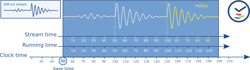
You can see how the running-time of a buffer always increments monotonically along with the clock-time. Buffers are played when their running-time is equal to the clock-time - base-time. The stream-time represents the position in the stream and jumps backwards when repeating.
Clock providers
A clock provider is an element in the pipeline that can provide a GstClock object. The clock object needs to report an absolute-time that is monotonically increasing when the element is in the PLAYING state. It is allowed to pause the clock while the element is PAUSED.
Clock providers exist because they play back media at some rate, and this rate is not necessarily the same as the system clock rate. For example, a sound card may play back at 44.1 kHz, but that doesn't mean that after exactly 1 second according to the system clock, the sound card has played back 44100 samples. This is only true by approximation. In fact, the audio device has an internal clock based on the number of samples played that we can expose.
If an element with an internal clock needs to synchronize, it needs to estimate when a time according to the pipeline clock will take place according to the internal clock. To estimate this, it needs to slave its clock to the pipeline clock.
If the pipeline clock is exactly the internal clock of an element, the element can skip the slaving step and directly use the pipeline clock to schedule playback. This can be both faster and more accurate. Therefore, generally, elements with an internal clock like audio input or output devices will be a clock provider for the pipeline.
When the pipeline goes to the PLAYING state, it will go over all elements in the pipeline from sink to source and ask each element if they can provide a clock. The last element that can provide a clock will be used as the clock provider in the pipeline. This algorithm prefers a clock from an audio sink in a typical playback pipeline and a clock from source elements in a typical capture pipeline.
There exist some bus messages to let you know about the clock and clock providers in the pipeline. You can see what clock is selected in the pipeline by looking at the NEW_CLOCK message on the bus. When a clock provider is removed from the pipeline, a CLOCK_LOST message is posted and the application should go to PAUSED and back to PLAYING to select a new clock.
For more detail please refer: https://gstreamer.freedesktop.org/documentation/application-development/advanced/clocks.html?gi-language=c
3 Appendix A - Input Configuration File (input.cfg)
The example configuration files are stored at /media/card/config/ folder.
Common Configuration:
It is the starting point of common configuration.
Num of Input:
Provide the number of inputs. This is always 1 for this design.
Output:
Select the video interface.
Options: SDI or DP
Out Type:
Options: display, record, and stream
Display Rate:
Pipeline frame rate.
Options: 30 FPS or 60 FPS for each stream.
Exit:
It indicates to the application that the configuration is over.
Input Configuration:
It is the starting point of the input configuration.
Input Num:
Starting Nth input configuration.
Options: 1
Format:
The format of input data is XV20
Input Type:
Input source type.
Options: SDI, File, Stream
Uri:
File path or Network URL. Applicable for file playback and Stream-in pipeline only. Supported file formats for playback are ts, mp4, and mkv.
Options: file:///media/usb/abc.ts (for file path), udp://192.168.25.89:5004/ (for Network streaming, Here 192.168.25.89 is IP address and 5004 is port number)
Raw:
To tell the pipeline is processed or pass-through.
Options: True, False
Width:
The width of the live source.
Options: 3840, 1920
Height:
The height of the live source.
Options: 2160, 1080
Exit:
It indicates to the application that the configuration is over.
Encoder Configuration:
It is the starting point of encoder configuration.
Encoder Num:
Starting Nth encoder configuration.
Options: 1
Encoder Name:
Name of the encoder.
Options: AVC, HEVC
Profile:
Name of the profile.
Options: baseline, main or high for AVC. Main for HEVC.
Rate Control:
Rate control options.
Options: CBR, VBR, and low-latency.
Filler Data:
Filler Data NAL units for CBR rate control.
Options: True, False
QP:
QP control mode used by the VCU encoder.
Options: Uniform or Auto
L2 Cache:
Enable or Disable L2Cache buffer in encoding process.
Options: True, False
Latency Mode:
Encoder latency mode.
Options: normal, sub_frame
Low Bandwidth:
If enabled, decrease the vertical search range used for P-frame motion estimation to reduce the bandwidth.
Options: True, False
Gop Mode:
Group of Pictures mode.
Options: Basic, low_delay_p, low_delay_b
Bitrate:
Target bitrate in Kbps
Options: 1-60000
B Frames:
Number of B-frames between two consecutive P-frames
Options: 0-4
Slice:
The number of slices produced for each frame. Each slice contains one or more complete macroblock/CTU row(s). Slices are distributed over the frame as regularly as possible. If slice-size is defined as well more slices may be produced to fit the slice-size requirement
Options:
4-22 4Kp resolution with HEVC codec
4-32 4Kp resolution with AVC codec
4-32 1080p resolution with HEVC codec
4-32 1080p resolution with AVC codec
GoP Length:
The distance between two consecutive I frames
Options: 1-1000
GDR Mode:
It specifies which Gradual Decoder Refresh(GDR) scheme should be used when gop-mode = low_delay_p
Options: Horizontal, Vertical, Disabled
GDR mode is currently supported with LLP1/LLP2 low-delay-p use-cases only
Entropy Mode:
It specifies the entropy mode for H.264 (AVC) encoding process
Options: CAVLC, CABAC, Default
Max Picture Size:
It is used to curtail instantaneous peak in the bit-stream. When it is enabled, max-picture-size value is calculated and set with 10% of AllowedPeakMargin.
i.e. max-picture-size = (TargetBitrate / FrameRate) * 1.1
Options: TRUE, FALSE
It works in CBR/VBR rate-control only
Preset:
Options: HEVC_HIGH, HEVC_MEDIUM, HEVC_LOW, AVC_HIGH, AVC_MEDIUM, AVC_LOW, Custom
Exit
It indicates to the application that the configuration is over.
Record Configuration:
It is the starting point of record configuration.
Record Num:
Starting Nth record configuration.
Options: 1
Out File Name:
Record file path.
e.g. /media/usb/abc.ts
Duration:
Duration in minutes.
Options: 1-3
Exit
It indicates to the application that the configuration is over.
Streaming Configuration:
It is the starting point of streaming configuration.
Streaming Num:
Starting Nth Streaming configuration.
Options: 1
Host IP:
The host to send the packets to
Options: 192.168.25.89 or Windows PC IP
Port:
The port to send the packets to
Options: 5004, 5008, 5012 and 5016
Exit
It indicates to the application that the configuration is over.
Audio Configuration:
It is the starting point of the audio configuration.
Audio Enable:
Enable or Disable audio in pipeline.
Options: True, False.
Audio Format:
The format of the audio.
Options: S24_32LE.
Sampling Rate:
To set the audio sampling rate.
Options: 48000.
Num Of Channel:
The number of audio channels.
Options: 2.
Volume:
To set the volume level. The default value is 2.0.
Options: 0.0-10.0.
Exit
It indicates to the application that the configuration is over.
4 Appendix B - SDI-Rx/Tx Link-up and GStreamer Commands
This section covers configuration of SDI-Rx using media-ctl utility and SDI-Tx using modetest utility, along with demonstrating SDI-Rx/Tx link-up issue and steps to switch resolution. It also contains sample GStreamer SDI Low-Latency XV20 pipelines for Display, Record, Stream-In and Stream-Out use-cases.
Run the below command to check the SDI link status and output format of the SDI input source. Run the below command for all media nodes to print media device topology where mediaX represents different media nodes. In the topology, log look for the v_smpte_uhdsdi_rx_ss string to identify the SDI input source media node. The media-ctl command generated as part of petalinux bsp will support all the vcu supported formats like NV12, NV16, XV15 and XV20.
$ media-ctl -p -d /dev/mediaX
Check resolution and frame-rate of v_smpte_uhdsdi_rx_ss node.
# media-ctl -d /dev/media0 -p -----> media node for SDI input source
Media controller API version 5.4.0

Media device information
------------------------
driver          xilinx-video
model           Xilinx Video Composite Device
serial
bus info
hw revision     0x0
driver version  5.4.0

Device topology
- entity 1: vcap_sdirx output 0 (1 pad, 1 link)
            type Node subtype V4L flags 0
            device node name /dev/video0  -----> Video node for SDI input source
        pad0: Sink
                <- "a0030000.v_smpte_uhdsdi_rx_ss":0 [ENABLED]

- entity 5: a0030000.v_smpte_uhdsdi_rx_ss (1 pad, 1 link)
            type V4L2 subdev subtype Unknown flags 0
            device node name /dev/v4l-subdev0
        pad0: Source
                [fmt:UYVY10_1X20/3840x2160@1001/60000 field:none]
                [dv.detect:BT.656/1120 3840x2160p60 (4400x2250) stds:CEA-861 flags:can-reduce-fps,CE-video,has-cea861-vic]  ---> SDI-Rx link up
                -> "vcap_sdirx output 0":0 [ENABLED]
When SDI source is connected to 4Kp60 resolution, it shows:
Check resolution and frame-rate of dv.detect under v_smpte_uhdsdi_rx_ss node.
When the SDI source is not connected, it shows:
# media-ctl -d /dev/media0 -p -----> media node for SDI input source
Media controller API version 5.4.0

Media device information
---[  320.147856] xilinx-sdirxss a0030000.v_smpte_uhdsdi_rx_ss: Video not locked!
---------------------
driver          xilinx-video
model           Xilinx Video Composite Device
serial
bus info
hw revision     0x0
driver version  5.4.0

Device topology
- entity 1: vcap_sdirx output 0 (1 pad, 1 link)
            type Node subtype V4L flags 0
            device node name /dev/video0  -----> Video node for SDI input source
        pad0: Sink
                <- "a0030000.v_smpte_uhdsdi_rx_ss":0 [ENABLED]

- entity 5: a0030000.v_smpte_uhdsdi_rx_ss (1 pad, 1 link)
            type V4L2 subdev subtype Unknown flags 0
            device node name /dev/v4l-subdev0
        pad0: Source
                [dv.query:no-lock]     ----------------> link is not detected
                -> "vcap_sdirx output 0":0 [ENABLED]
Check resolution and frame-rate of v_smpte_uhdsdi_rx_ss node.
Modetest commands:
Modetest command for 4Kp60 Display
$ modetest -M xlnx -s 34:3840x2160-60@XV20 -w 34:sdi_mode:5 -w 34:sdi_data_stream:8 -w 34:is_frac:0
Modetest command for 4Kp30 Display
$ modetest -M xlnx -s 34:3840x2160-60@XV20 -w 34:sdi_mode:4 -w 34:sdi_data_stream:8 -w 34:is_frac:0
Modetest command for 1080p60 Display
$ modetest -M xlnx -s 34:1920x1080-60@XV20 -w 34:sdi_mode:2 -w 34:sdi_data_stream:2 -w 34:is_frac:0
Modetest command for 4Kp59.94 Display
$ modetest -M xlnx -s 34:3840x2160-60@XV20 -w 34:sdi_mode:5 -w 34:sdi_data_stream:8 -w 34:is_frac:1
Modetest command for 4Kp29.97 Display
$ modetest -M xlnx -s 34:3840x2160-60@XV20 -w 34:sdi_mode:4 -w 34:sdi_data_stream:8 -w 34:is_frac:1
Modetest command for 1080p59.94 Display
$ modetest -M xlnx -s 34:1920x1080-60@XV20 -w 34:sdi_mode:2 -w 34:sdi_data_stream:2 -w 34:is_frac:1
Follow the below steps to switch the SDI-Rx resolution from 1080p60 to 4Kp60.
Check current SDI Input Source Resolution (1080p60) by following the above-mentioned steps.
Run
vcu_gst_appfor current SDI resolution (1080p60) by executing the following command.
$ vcu_gst_app /media/card/config/input.cfg
Below configurations needs to be set in input.cfg for SDI-1080p60.
Common Configuration    : START
Num Of Input            : 1
Output                  : SDI
Out Type                : Display
Frame Rate              : 60
Exit

Input Configuration     : START
Input Num               : 1
Input Type              : SDI
Raw                     : TRUE
Width                   : 1920
Height                  : 1080
Format			: XV20
Exit
Change Resolution of SDI Input Source from 1080p60 to 4Kp60 by following the below steps.
Set the SDI source resolution to 4Kp60 (Home page → settings → display & Sound → Resolution → change to 4Kp60).
Save the configuration to take place the change.
Verify desired SDI Input Source Resolution (4Kp60) by following the above-mentioned steps.
SDI fractional frame rate is supported in this release. To enable the fractional frame rate for SDI-Tx,
is_frac=1needs to be set in the below pipelines.Run the following
gst-launch-1.0command to display raw SDI video using the GStreamer pipeline.
$ gst-launch-1.0 v4l2src device=/dev/video0 io-mode=4 ! video/x-raw ,format=NV16_10LE32, width=3840, height=2160, framerate=60/1 ! queue max-size-bytes=-1 ! fpsdisplaysink text-overlay=false video-sink="kmssink driver-name=xlnx async=false hold-extra-sample=true show-preroll-frame=false" text-overlay=false sync=false alsasrc device=hw:1,1 ! queue ! audioconvert ! audioresample ! audio/x-raw, rate=48000, channels=2, format=S24_32LE ! alsasink device="hw:1,0"
Run the following
gst-launch-1.0command to display processed(capture → encode → decode → display) SDI video using the GStreamer pipeline.
$ gst-launch-1.0 v4l2src device=/dev/video0 io-mode=4 ! video/x-raw, width=3840, height=2160, format=NV16_10LE32, framerate=60/1 ! omxh265enc qp-mode=auto gop-mode=basic gop-length=60 b-frames=0 target-bitrate=60000 max-picture-size=1100 num-slices=8 control-rate=constant prefetch-buffer=true low-bandwidth=false filler-data=true cpb-size=1000 initial-delay=500 ! video/x-h265, profile=main-422-10, alignment=au ! queue max-size-bytes=0 ! omxh265dec internal-entropy-buffers=5 low-latency=0 ! queue max-size-bytes=0 ! fpsdisplaysink text-overlay=false video-sink="kmssink driver-name=xlnx async=false hold-extra-sample=true show-preroll-frame=false" alsasrc device=hw:1,1 ! queue ! audioconvert ! audioresample ! audio/x-raw, rate=48000, channels=2, format=S24_32LE ! alsasink device="hw:1,0" -v
Run the following
gst-launch-1.0command to record SDI video using the GStreamer pipeline.
$ gst-launch-1.0 v4l2src device=/dev/video0 io-mode=4 num-buffers=3600 ! video/x-raw, width=3840, height=2160, format=NV16_10LE32, framerate=60/1 ! omxh265enc qp-mode=auto gop-mode=basic gop-length=60 b-frames=0 target-bitrate=60000 max-picture-size=1100 num-slices=8 control-rate=constant prefetch-buffer=true low-bandwidth=false filler-data=true cpb-size=1000 initial-delay=500 ! video/x-h265, profile=main-422-10, alignment=au ! queue max-size-bytes=0 ! mux. alsasrc device=hw:1,1 ! audio/x-raw, format=S24_32LE, rate=48000, channels=2 ! queue max-size-buffers=0 max-size-time=0 ! audioconvert ! faac ! aacparse ! queue max-size-bytes=0 ! mpegtsmux name=mux ! filesink location="/run/test.ts"
File location should be USB-3.0/SATA/RAMdisk to avoid the read-write bandwidth issue.
Run the following
gst-launch-1.0command to play the recorded file using the GStreamer pipeline.
$ gst-launch-1.0 uridecodebin uri="file:///run/test.ts" name=decode ! queue max-size-bytes=0 ! fpsdisplaysink text-overlay=false video-sink="kmssink driver-name=xlnx async=false hold-extra-sample=true show-preroll-frame=false" decode. ! audioconvert ! audioresample ! audio/x-raw, rate=48000, channels=2, format=S24_32LE ! alsasink device="hw:1,0"
File location should be USB-3.0/SATA/RAMdisk to avoid the read-write bandwidth issue.
Run the following
gst-launch-1.0command to stream-out SDI video using the GStreamer pipeline.
$ gst-launch-1.0 v4l2src device=/dev/video0 io-mode=4 ! video/x-raw, width=3840, height=2160, format=NV16_10LE32, framerate=60/1 ! omxh265enc qp-mode=auto gop-mode=basic gop-length=60 b-frames=0 target-bitrate=60000 max-picture-size=1100 num-slices=8 control-rate=constant prefetch-buffer=true low-bandwidth=false filler-data=true cpb-size=1000 initial-delay=500 periodicity-idr=60 ! video/x-h265, profile=main-422-10, alignment=au ! h265parse ! queue ! mux. alsasrc device=hw:1,1 ! audio/x-raw, format=S24_32LE, rate=48000, channels=2 ! queue ! audioconvert ! audioresample ! faac ! aacparse ! mpegtsmux name=mux ! rtpmp2tpay ! udpsink host=192.168.25.89 port=5004 buffer-size=60000000 max-bitrate=120000000 max-lateness=-1 qos-dscp=60 async=false
Here 192.168.25.89 is host/client IP address and 5004 is port number.
Run the following
gst-launch-1.0command to display stream-in SDI video using the Gstreamer pipeline where 5004 is port number.
$ gst-launch-1.0 udpsrc port=5004 buffer-size=60000000 caps="application/x-rtp, clock-rate=90000" ! rtpjitterbuffer latency=1000 ! rtpmp2tdepay ! tsparse ! video/mpegts ! tsdemux name=demux demux. ! queue ! h265parse ! video/x-h265, profile=main-422-10, alignment=au ! omxh265dec internal-entropy-buffers=5 ! queue max-size-bytes=0 ! fpsdisplaysink name=fpssink text-overlay=false video-sink="kmssink driver-name=xlnx async=false hold-extra-sample=true show-preroll-frame=false" demux. ! queue max-size-bytes=0 max-size-time=0 max-size-buffers=0 ! aacparse ! faad ! audioconvert ! audioresample ! audio/x-raw, rate=48000, channels=2, format=S24_32LE ! alsasink device="hw:1,0"
Commands to run interlaced mode
$ gst-launch-1.0 v4l2src io-mode=4 ! video/x-raw\(format:Interlaced\),interlace-mode=alternate,format=NV16_10LE32,width=1920,height=1080,framerate=30/1 ! omxh265enc target-bitrate=10000 control-rate=2 ! omxh265dec ! queue max-size-bytes=-1 ! kmssink bus-id=amba_pl@0:drm-pl-disp-drv connector-properties="props,sdi_mode=0,sdi_data_stream=2,is_frac=0" show-preroll-frame=false

$ gst-launch-1.0 v4l2src io-mode=4 ! video/x-raw\(format:Interlaced\),interlace-mode=alternate,format=NV16_10LE32,width=720,height=576,framerate=25/1 ! omxh265enc target-bitrate=4000 control-rate=2 ! omxh265dec ! queue max-size-bytes=-1 ! kmssink bus-id=amba_pl@0:drm-pl-disp-drv connector-properties="props,sdi_mode=1,sdi_data_stream=2,is_frac=0" show-preroll-frame=false

$ gst-launch-1.0 v4l2src io-mode=4 ! video/x-raw\(format:Interlaced\),interlace-mode=alternate,format=NV16_10LE32,width=720,height=486,framerate=30/1 ! omxh265enc target-bitrate=10000 control-rate=2 ! omxh265dec ! queue max-size-bytes=-1 ! kmssink bus-id=amba_pl@0:drm-pl-disp-drv connector-properties="props,sdi_mode=1,sdi_data_stream=2,is_frac=1" show-preroll-frame=false