Zynq UltraScale Plus MPSoC - PL Temperature and Voltage Monitor
Table of Contents
Requirements
- ZCU102 development board (This design example has been tested on silicon 4.0 rev1.0 board)
- SDK (2017.4 release and above)
Design Implementation
This design example initializes, configures and monitors PL on-chip temperature and various voltages from PMU Microblaze periodically. Following is the design implementation:- PMU Firmware application runs on PMU Microblaze. It registers a new module for monitoring PL on-chip temperature and voltages using PSU Sysmon driver APIs.
- This module initializes the System Monitor device driver instance.
- It runs the self-test on the device.
- It sets up the sequence registers to continuously monitor the following channels:
- PL temperature (Temp_PL)
- PL internal voltage (VCCINT)
- PL auxiliary voltage (VCCAUX)
- ADC positive (VREFP) and negative (VREFN) reference voltages
- PL Block RAM voltage (VCCBRAM)
- LPD (VCC_PSINTLP), FPD (VCC_PSINTFP) and PS auxiliary (VCC_PSAUX) voltages
- PL Auxiliary voltages (VAUX{0:15}) – These channel values are valid only when they are configured in the hardware design
- PL User defined voltages (VUser{0:3}) – These channel values are valid only when they are configured in the hardware design
- PL ADC power supply voltage (VCCADC)
- It enables the channel sequencer in continuous sequencer cycling mode to start the sequence.
- And it adds a scheduler task to read the latest on-chip temperature and voltages continuously for every 10 seconds and prints on the terminal
Application creation steps
- Create FSBL application either for A53 or for R5 processor
- Create PMU Firmware application. Download this zip file
,extract and add the extracted source files to the PMU Firmware application. This creates a new custom module in PMU Firmware which initializes sysmon and monitors PL temperature and voltages periodically in continuous sequencer cycling mode. Please refer to "Custom Module Usage" section in chapter 10 in Zynq UltraScale+ MPSoC Software Developer Guide for reference
- Enable scheduler module by defining ENABLE_SCHEDULER macro and rebuild the PMU Firmware application
Steps to create boot image
- In SDK, go to Xilinx -> Create Boot Image. Create Boot Image window appears as below

- Select Zynq MP in Architecture category. Select Create new BIF file option
- Browse and select path for Output BIF file path
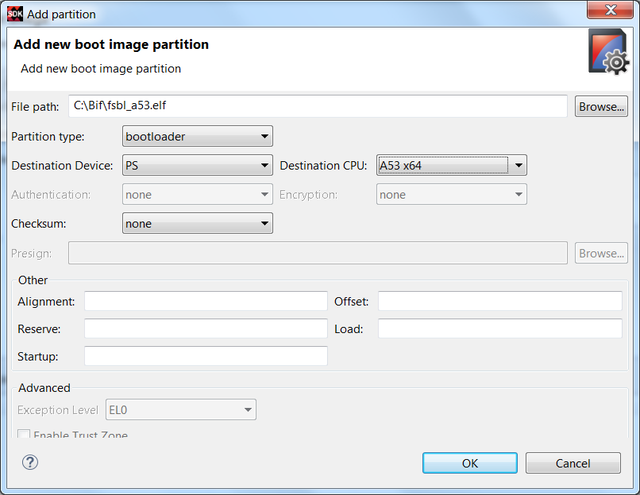
- Click on Add button to add partition. Select fsbl_a53 executable path at File path. Select Partition type as bootloader, Destination Device as PS and Destination CPU as A53 x64. Click OK. Please see the below image for reference
- Click on Add button again to add BIT file partition. Select PL bit file path at File path. Select Partition type as datafile and Destination Device as PL. Click OK. Please check below image for reference

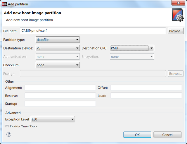
- Click on Add button to add PMU Firmware partition. Select pmu_firmware executable file path at File path. Select Partition type as datafile, Destination Device as PS and Destination CPU as PMU. Click OK. Please see the below image for reference
- Now click on Create Image. BOOT.BIN is created at Output BIF file path. Copy the BOOT.BIN to SD card and power-on ZCU102 board in SD boot mode. And observe the prints on UART terminal
Snippet of BIF file
Below is the snippet of BIF file created with the steps mentioned above//arch = zynqmp; split = false; format = BIN
the_ROM_image:
{
[fsbl_config]a53_x64
[bootloader]C:\Images\fsbl_a53.elf
[destination_device = pl]C:\Images\design_1_wrapper.bit
[destination_cpu = pmu]C:\Images\pmu_fw.elf
}
Related Links
© Copyright 2019 - 2022 Xilinx Inc. Privacy Policy