ZU+ Example - Deep Sleep
Table of Contents
Introduction
This example explains procedure to put system in deep-sleep mode starting from Vivado isolation design, petalinux for APU, TCM baremetal for RPU.
This includes:
http://www.wiki.xilinx.com/ZU%EF%BC%8B+Example+-+Deep+Sleep+with+PS+SysMon+in+Sleep+Mode during deep sleep.
directly jump to section Generate HDF.
To create a new block design follow below steps:
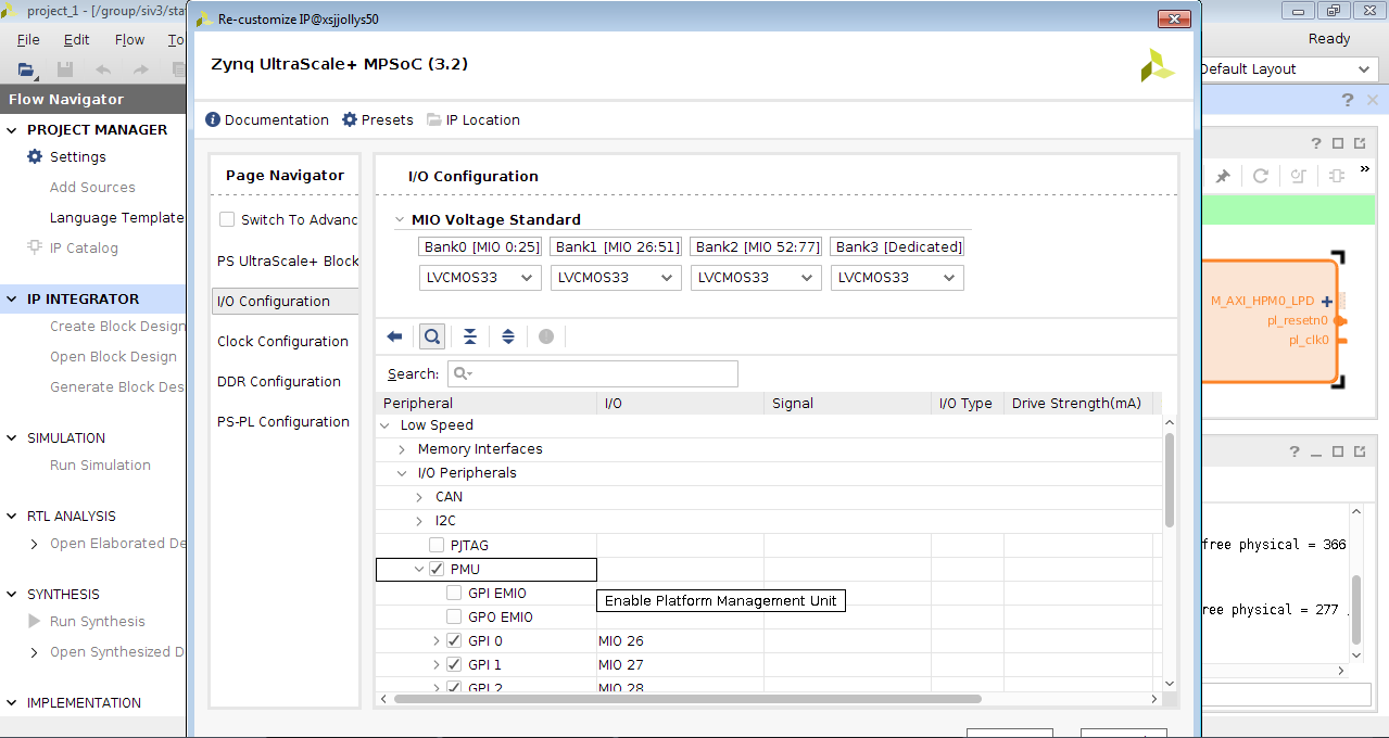
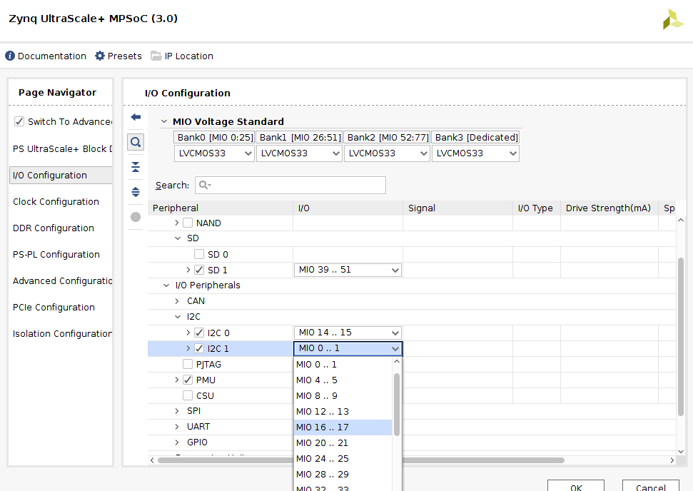
IMPORTANAT: Make sure that PMU is enabled (in I/O Configuration → Low Speed → I/O Peripherals → PMU) as per below image otherwise domain power on/off won't work.
Notes:
Note: Isolation configurations creates isolation between different blocks and may restrict access to other blocks on system. Isolation configurations needs extra care of adding minimum subsystems and assigning required master/slaves to each system. If isolation configuration is not done properly, system may not boot. If you need, you may use example block design (with isolation config enabled) as reference.
Add APU subsystem

Add RPU subsystem
Below is an example:
Note: User needs to know minimum configuration required based on their system. Refer Isolation Configuration Consideration for more information on isolation configuration.
Add RPU1 subsystem
Below is an example:
Add APU_secure subsystem
Below is an example:

Note: You may need to change Secure/Non-secure settings according to your other sub system setting.
This includes:
- ZCU102 design with isolation config using Vivado and HDF generation
- Generate config object from HDF
- petalinux on APU
- RPU baremetal application running from TCM
- Deep Sleep mode
Requirements
- ZCU102 development board (This design example has been tested on silicon 3.0 revD board).
- Vivado (2017.1 or later release)
- SDK (2017.1 or later release)
- Petalinux (2017.1 or later release)
Known Issues
With production silicon, the PMU is driven by the SysOsc, which normally runs at 200 MHz. This is different from pre-production silicon where the PMU is driven by the 33 MHz PS Ref clock instead, and consumes much lower power. This means that for the production silicon to get to the target deep sleep power (35 mW), the SysMon must be powered down. Refer to this design example on how to power down the SysMon:http://www.wiki.xilinx.com/ZU%EF%BC%8B+Example+-+Deep+Sleep+with+PS+SysMon+in+Sleep+Mode during deep sleep.
Vivado: Generate HDF with Isolation config
This section explains procedure to create new project in Vivado, isolation configuration and exporting bit-stream/HDF files.Create a new Vivado project
Start Vivado. Once Vivado GUI is ready, create a new zcu102 project :- Go to File → New Project → Next
- Select Project name and workspace location. Then press "Next" button.
- Select project type as "RTL Project". Check the box indicating "Do not Specify sources at this time". Then press "Next" button.
- Select "Boards" in "Select" option. Select "Zynq UltraScale+ ZCU102 Evaluation Board" from board list. Press "Next" button.
- Verify project summary and click "Finish" button.
Create Block Design
One can create new block design (if familiar with creating designs using Vivado) or import already created block design (basic working design).Import already created block design
Import example block design by following steps mentioned below anddirectly jump to section Generate HDF.
- Download attached ready block design file
- Click on TCL console in Vivado.
In the line on the bottom where it says "type tcl command here", type below command to import block design:
source <path to tcl file>/isolation_config.tcl
Create new block design
To create a new block design follow below steps:
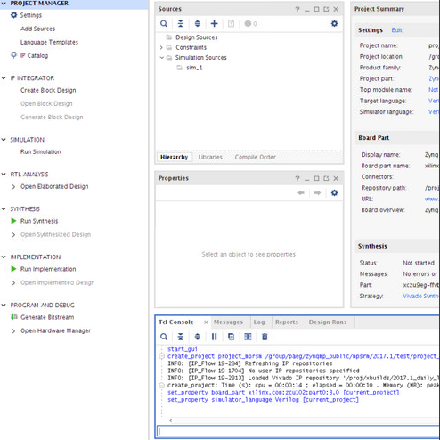
- In the Flow Navigator → IP INTEGRATOR, click on "Create Block Design" option.
- Enter Design name. Keep "Directory" and "Specify sources set" to default values (Directory: <Local to Project> and Specify sources set: Design Sources). Click on "OK" button.
- Go to "Diagram" Window. If "Diagram" window doesn't appear on main screen, it can be opened from Windows → Diagram. Press '+' button to add IP. Add "Zynq UltraScale+ MPSoC" IP. Process will run and IP will be added.

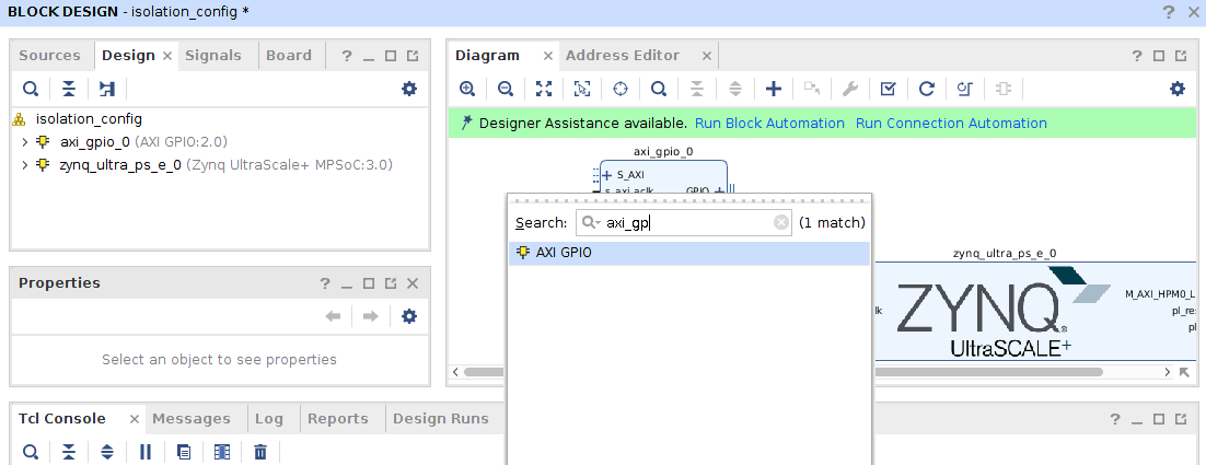
- Go to "Diagram" Window. If "Diagram" window doesn't appear on main screen, it can be opened from Windows → Diagram. Press '+' button to add IP. Add "AXI GPIO" IP. Process will run and IP will be added.
- Click on "Run Connection Automation" when designer assistant is available. Select all components and click on "OK" button. Run this multiple times until all connections are done (and no more assistant is available).
Customize ZYNQ IP
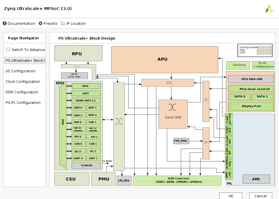
This step is useful to customize "Zynq UltraScale+ MPSoC" and isolation configuration.- Go to "Diagram" Window. Double click on "Zynq UltraScale+ MPSoC" block. (or right click and then click on "Customize Block" option).

- On the "Page Navigator" bar, check the "Switch to Advanced" checkbox. On the click, few more options will be available.
Configure required peripheral(s)
This is used to add/remove peripherals in block based on requirement. This step can be skipped if default peripherals suits the requirement.- Go to I/O configuration option.
- Expand peripheral options (Low Speed, High Speed, Reference Clocks) and find the required peripherals. Once can search peripheral name in search box also.
- Check peripheral to enable(add) it or uncheck to disable(remove) it.
One can also go to PS Ultrascale + Block Design and double click on slave to configure it.
IMPORTANAT: Make sure that PMU is enabled (in I/O Configuration → Low Speed → I/O Peripherals → PMU) as per below image otherwise domain power on/off won't work.
Notes:
- All below steps are available after when you switch to advanced option.
- One has to be very sure about peripherals required for the system. System with design may not work if mandatory peripherals are not selected.
Enable Isolation Config
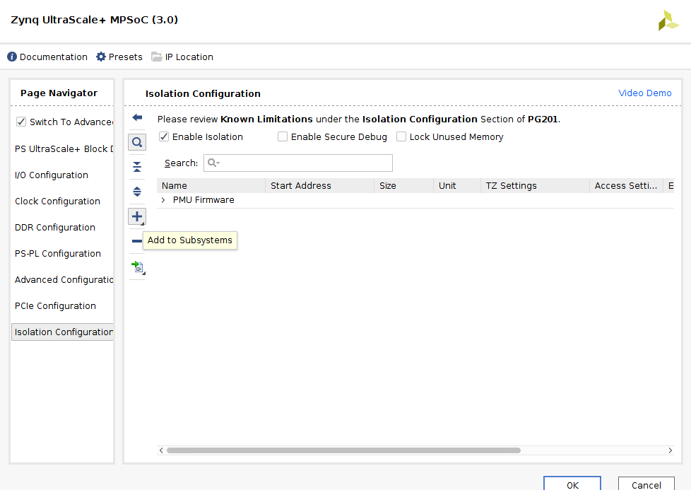
Note: Isolation configurations creates isolation between different blocks and may restrict access to other blocks on system. Isolation configurations needs extra care of adding minimum subsystems and assigning required master/slaves to each system. If isolation configuration is not done properly, system may not boot. If you need, you may use example block design (with isolation config enabled) as reference.
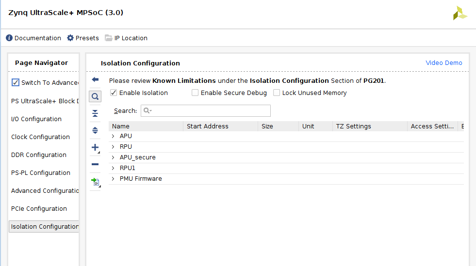
- Click on "Isolation Configuration" option. Options for configuration will be shown on right side.
- Check on "Enable Isolation" checkbox. Keep reset checkbox as it is (Enable Secure Debug: Unchecked and Lock Unused Memory: Unchecked).
Add Subsystems
By default there will be single subsystem present named "PMU Firmware". More subsystems can be added based on requirements.Add APU subsystem
- Click on "Isolation Configuration" option. Options for configuration will be shown on right side.
- Click on "+" button to add new subsystem. Add subsystem named "APU" and press "ENTER" to add it.
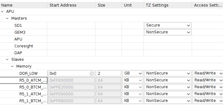
- Right click on "APU" subsystem and Click on "Add Master" option. Add "APU" from Processors list.
- It is required for Linux as Linux is non-secure
- secure master:
- SD: it is for reboot from SD card, as it needs to load firmware to OCM
- Master
- APU
- DAP if you need debugging
- non-secure master:
- anything master doesn't need to access secure slaves
- DDR
- UART
- And others
- secure master:
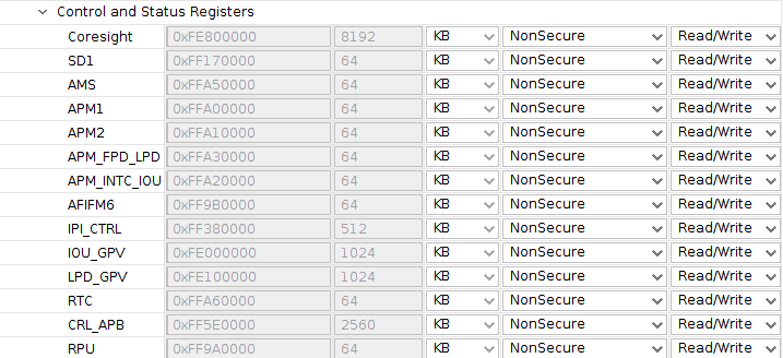
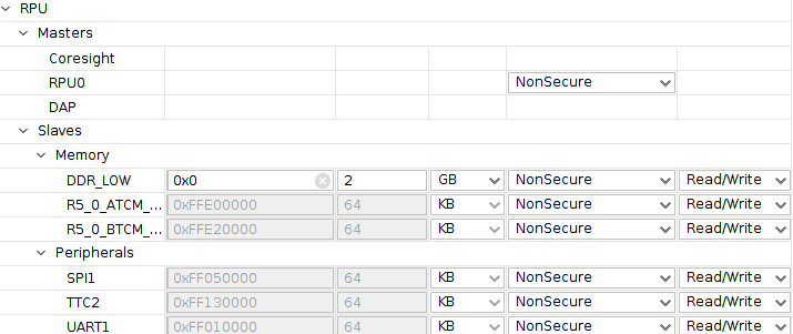
Add RPU subsystem
- Click on "Isolation Configuration" option. Options for configuration will be shown on right side.
- Click on "+" button to add new subsystem. Add subsystem named "RPU" and press "ENTER" to add it.
- Right click on "RPU" subsystem and Click on "Add Master" option. Add "RPU0" from Processors list.
- non-secure masters:
- RPU0
- non-secure slaves:
- DDR_LOW
- TCM_0 A/B
- devices accessed by RPU0
- non-secure masters:
Below is an example:
Note: User needs to know minimum configuration required based on their system. Refer Isolation Configuration Consideration for more information on isolation configuration.
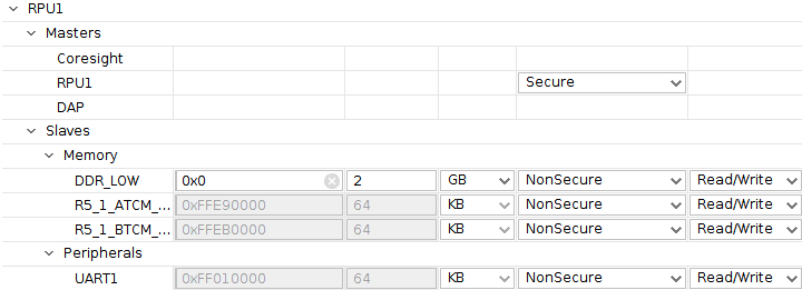
Add RPU1 subsystem
- Click on "Isolation Configuration" option. Options for configuration will be shown on right side.
- Click on "+" button to add new subsystem. Add subsystem named "RPU1" and press "ENTER" to add it.
- Right click on "RPU1" subsystem and Click on "Add Master" option. Add "RPU1" from Processors list.
- non-secure masters:
- RPU1
- non-secure slaves:
- DDR_LOW
- TCM_1 A/B
- devices accessed by RPU1
- non-secure masters:
Below is an example:
Add APU_secure subsystem
- Click on "Isolation Configuration" option. Options for configuration will be shown on right side.
- Click on "+" button to add new subsystem. Add subsystem named "APU_secure" and press "ENTER" to add it.
- Right click on "APU_secure" subsystem and Click on "Add Master" option. Add "APU" from Processors list.
- APU secure: It is required for FSBL and ATF
- secure master:
- SD
- master:
- APU
- secure slaves:
- OCM
- CRF_APB
- CRL_APB
- IOU_SLCR
- EFUSE
- secure master:
Below is an example:
Note: You may need to change Secure/Non-secure settings according to your other sub system setting.
Generate Hardware Description File(HDF)
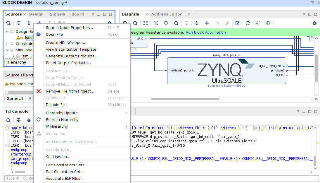
- Go to "Sources" window. If "Sources" window doesn't appear on main screen, it can be opened from Windows → Sources.
- In "Sources" window, right click on ".bd" file (under Design Sources). From the right click menu list, click on "Create HDL Wrapper". Keep default option(Let Vivado manage wrapper...) and press "OK".
- In the Flow Navigator → IP INTEGRATOR, click on "Generate Block Design" option. Keep default option and click on "Generate" option.
- In the Flow Navigator → SIMULATION, click on "Run Simulation" option. From the available options click on "Run Behavioral Simulation".
- In the Flow Navigator → PROGRAM and DEBUG, click on "Generate Bitstream" option.
- Go to File → Export → Export Hardware
- Check "Include bitstream in HDF" option. Set export path if required or keep it default(<Local to Project>). Click "OK".
- In case of default path, HDF file will be generated at <workspace>/<project_name>/<project_name>.sdk/<block_name>.hdf.
Configuration Object
Configuration Object file Generated by PetaLinux tool chain and Vivado is attached below.Subsystems -
1) Linux Subsystem
Master -
- APU
- DDR
- L2 Cache
- OCM Bank 0, 1, 2 and 3
- I2C0
- I2C1
- SD1
- QSPI
- PL
2) R5-0 Subsystem
Master -
- RPU0
- TCM Bank 0 - A
- TCM Bank 0 - B
3) R5-1 Subsystem
Master -
- RPU1
- TCM Bank 1 - A
- TCM Bank 1 - B
Petalinux on APU
Create petalinux project
Run below commands from bash terminal to create project petalinux.source <petalinux-install-dir>/settings.sh petalinux-create -t project --template zynqmp -s <path-to-petalinux-bsp>/xilinx-zcu102-v2017.1-final.bsp
Configure petalinux to use hdf generated from Vivado design
petalinux-config --get-hw-description=<path-to-hdf> --oldconfig
Build petalinux project
petalinux-build
RPU baremetal application running from TCM
Refer ZU+ Example - Deep Sleep with Periodic Wake-up to build and run baremetal applications.
Note: To use new generated design, in application create step, instead of selecting "ZCU102_hw_platfrom" as target, follow below steps:
- Create on "New" in Hardware Platform option.
- Provide custom hardware name and select hdf file generated from Vivado.
- Press Finish.
- Follow reset of steps same as mentioned in above page.
Running Linux on APU and RPU baremetal app
One can use either create add RPU application in BOOT.bin along with other things(fsbl, pmufw, bl31, atf, bit file generated from block design) and run Linux and RPU app using SD boot mode or can load RPU application from XSDB when Linux is up. Following steps describes XSDB way to load RPU application.Run Linux on APU
Boot Linux using petalinux-boot command from petalinux project directory.petalinux-boot --jtag --kernel --fpga
When Linux is up, disable CPU idle by following commands:
root@plnx_aarch64:~# echo 1 > /sys/devices/system/cpu/cpu0/cpuidle/state1/disable
root@plnx_aarch64:~# echo 1 > /sys/devices/system/cpu/cpu1/cpuidle/state1/disable
root@plnx_aarch64:~# echo 1 > /sys/devices/system/cpu/cpu2/cpuidle/state1/disable
root@plnx_aarch64:~# echo 1 > /sys/devices/system/cpu/cpu3/cpuidle/state1/disable
Perform following command on xsdb to load and run RPU app.
xsdb% connect xsdb% target -set -filter {name =~ "Cortex-R5 #0"} xsdb% rst -c xsdb% exec sleep 2 xsdb% dow <deeps_sleep_rtc_wakeup.elf> xsdb% mask_write 0xff9a0000 0x8 0x8 xsdb% con- Note: As RPU is running in split mode, below steps are needed.
RPU1 should forced power down after linux boot. This is alternate to running another app on RPU1 which calls PmInitFinalize(). Without this PMUFW will not power down unused nodes considering that RPU1 might be using it and hence FPD will not be powered down.
(Till v2018.1)
root@plnx_aarch64:~# echo request_wakeup 8 1 0 1 > /sys/kernel/debug/zynqmp_pm/power
root@plnx_aarch64:~# echo force_powerdown 8 >  /sys/kernel/debug/zynqmp_pm/power
(For v2018.2 and above)
root@plnx_aarch64:~# echo request_wakeup 8 1 0 1 > /sys/kernel/debug/zynqmp-firmware/pm
root@plnx_aarch64:~# echo force_powerdown 8 >  /sys/kernel/debug/zynqmp-firmware/pm
Related Links
© Copyright 2019 - 2022 Xilinx Inc. Privacy Policy