Table of Contents
This page provides an introduction to the "Accelerated Image Classification via Binary Neural Network" (short AIC) design example.
This design example demonstrates how moving software implemented neural networks can be dramatically accelerated via Programmable Logic. In this design a Binary Neural Network (BNN) is implemented. Depending on silicon platform an acceleration of 6,000 to 8,000 times is demonstrated. Via the graphical user interface the user can see metrics, images and classification results.
The work is based on top of the work of the Xilinx Research Lab. More information can be found here:
Inference of quantized neural networks on heterogeneous all-programmable devices (DATE 2018)
FINN: A Framework for Fast, Scalable Binarized Neural Network Inference (FPGA 2017)
Scaling Binarized Neural Networks on Reconfigurable Logic (PARMA-DITAM 2017)
Scaling Neural Network Performance through Customized Hardware Architectures on Reconfigurable Logic (ICCD 2017)
You can also checkout following repositories:
https://github.com/Xilinx/BNN-PYNQ
https://github.com/Xilinx/QNN-MO-PYNQ
For any questions please contact Missing Link Electronics (MLE).
The AIC Demo is available for following Platforms:
| Board | Device | Revision |
| ZCU102 | XCZU9EG | Rev D2, Rev 1.0, Rev 1.1 |
| Ultra96 | XCZU3EG | V1 |
Document History
| Date | Version | Author | Description of Revisions |
| 2018-03-26 | V0.1 | Andreas Schuler (MLE) | Initial Document |
| 2018-04-30 | V1.0 | Andreas Schuler (MLE) | first release |
| 2018-05-03 | V1.1 | Andreas Schuler (MLE) | Add reference to Xilinx Research Lab |
| 2018-12-14 | V1.1 | Andreas Schuler (MLE) | Update Document to latest changes |
Implementation
| Implementation Details | |
| Design Type | PS & PL |
| SW Type | PetaLinux/Ubuntu, QT5.4.2, OpenCV-3.3.0 |
| CPUs | Quad A53 |
| PS Features | DDR, GPU, Mali400 |
| PL Cores | HLS BNN IP |
| Boards/Tools | ZCU102 or Ultra96, USB Hub, Mouse, Logitech HD Pro Webcam Brio/C920/C525/C615, UHD or HD DisplayPort Monitor |
| Xilinx Tools Version | Vivado 2017.3 |
| Other Details | Vivado Base |
| Files Provided | |
| 20180814_aicdemo_projectfiles_20181.zip | Zip file (2018.1 Vivado/HLS/Petalinux project) |
| 20180814_zcu102_ultra96_aicdemo_20181.zip | Zip file 2018.1 Image for AIC Demo for ZCU102 and Ultra96 |
| 20180424_zcu102_ultra96_aicdemo.img | Image of AIC Demo for ZCU102 and Ultra96 |
| 20180424_aicdemo_projectfiles.zip | Zip file (Vivado/HLS/Petalinux project) |
| AIC_road_signs.zip | Printable Roadsigns |
1. Description/Summary
This example demonstrates how this image classification design developed by Xilinx can rapidly classify German road signs with a ZCU102 or Ultra96board. This is done using a Binary Neural Network (BNN) implemented in FPGA logic. The image source for the design is either a database with road sign images or a USB-webcam. The output of the BNN is shown on a Monitor. The application can be controlled with a GUI that allows is changing the image sources, and to start and stop the classification process. The GUI is implemented using the Ubuntu Desktop is running on top of a Petalinux on the Processing system. Below you can see the structure of the GUI. On the left side you see the current classified image and the performance of the BNN. To the right of the large status window are the last three classified images with top-5 results are shown. An explanation on how to control the application can be found in section Run the design.
 |
| Fig. 1.1 GUI Overview |
The Accelerated Image Classification via Binary Neural Network design example classifies a road sign found in a scene.
The 1080p scene is resized to 4 layers, each layer is tiled by a 32x32 pixel kernel, this results in 202 tiles.
- 1st layer: 54x32 pixel, 6 tiles
- 2nd layer: 78x44 pixel, 36 tiles
- 3rd layer: 110x64 pixel, 160 tiles
The horizontal and vertical strides are 4 pixel ~13%.
Thus, the minimum size sign that may be recognized out of a 1080p scene is: hight 1080 to 200pixel in scenery.
After tiling, all tiles gets transfered via DMA to the HW BNN which classifies each tile and put the results into a result register.
All results get sorted by class and from each class the winner is taken to the final group. The top 5 results of the final group are displayed in the GUI.
The confidence percentage is calculated by the softmax algorithm which is commonly used for neural networks.
2. Block Diagram
| Fig. 2.1 Functional Block Diagram |
3. Overview and general information
3.1 General
All paths in this documentation are stated relativ to the source folder, which is referenced by the
foldername aic/.
This design provides:
- source files for running the BNN in hardware and software
- SD-Card image with prebuilt petalinux kernel, Ubuntu Desktop, required Software and Programmable Logic design files
- Zip file for ZCU102 and Ultra96 board
All designs are built and tested using a Linux host machine. This design has not been tested or implemented for a Windows machine.
3.2 Sources and Folder Structure
3.2.1 GUI
Holds all the sources relevant for the software part. Under aic/src_sw/xlx_aic_gui/ all the
sourcefiles for the GUI itself can be found. The GUI can be split into three parts.
- Opencvworker: opens the images and does minor preprocessing for the GUI. It then sends the images to the Playerworker
- Playerworker: The Playerworker is the middleman between Opencvworker, GUI and BNN. It forwards the images received from the opencvworker to the GUI and the actual image processing (tiling, BNN, analysis).
- GUI: The GUI splits in two files. The gui.cpp handles all the labels created with QTCreator i.e. printing the values for the tiles per second-metric. The xlx_aic_gui.cpp connects the slots of the 3 workers. Thus, this file becomes important when values etc. need to be exchanged between i.e. the Opencvworker and the gui.
3.2.2 Processing
The files for the actual processing can be found under aic/src_sw/xlx_aic_proc/ and aic/src_hw/. The files under src_sw hold the files implementing the preprocessing and analysis. Most importantly the dataset_proc.cpp needs to be mentioned as it can be viewed as the main.cpp of pre-/postprocessing. The camera.cpp is very similar but neglects the tiling algorithms. In src_hw files of the BNN git repository for the PYNQ board (BNN-PYNQ <https://github.com/Xilinx/BNN-PYNQ>) as well as the vivado sources and *.tcl scripts can be found.
3.2.3 PetaLinux
In the folder aic/src_sw/<platform name>-petalinux all files to rebuild the BOOT.BIN file of the linux system can be found. This is needed if the FPGA design was modified and it is needed to deploy the rebuilt bitstream to the system.
4. Bing up the system and run the design
This section describes how to set up the board and peripherals, then explains how to
run the design. All this is based on the pre built design, that can be found on the provided SD-Card
image. If you would like to modify or rebuild parts of the design, please look at section Rebuild the
Design from source.
4.1 Requirements
Required hardware and peripherals to successfully run the design:
• Linux host system (for rebuild)
• Ultra96 Rev. D or ZCU102 Rev. D board + Power Adapter
• 4K or HD Monitor with Display Port (Designs have been tested with the LG27MU67-B)
• SD-Card with at least 8GB (16GB recommended) (Ultra96: microSD, ZCU102: SD)
• micro USB cable for the use of the terminal emulator
• Webcam with USB cable: The webcam needs to output YUYV pixel format (The design has been tested with the listed on top)
• mouse and keyboard
• USB 3.0 hub
• When using the ZCU102 board: ethernet cable, Xilinx USB3 micro-B adapter (USB3-micro-b-plug Adapter)
4.2 Prepare the Ready to Run SD-Card
The provided SD-Card image has to be written onto the SD-Card. This overwrites all data and
partitions that exist on the SD-Card so far.
On a linux host system:
- Unzip 20180418_zcu102_ultra96_aicdemo.zip
- Find out the device name of your SD-Card by running df -h with your SD-Card mounted. After that unmount your SD-Card.
- Run dd bs=4M if=20180418_zcu102_ultra96_aicdemo.img of=/dev/<nameOfYourCard> conv=fsync. This step will take a while.After this process, the SD-Card will have two partitions: one small one formatted with fat32 containing a BOOT.Bin and image.ub file, and one large one formatted with ext3 containing a root file system.
On a Windows host system:
A bootable SD can be created as follows:
- Unzip 20180418_zcu102_ultra96_aicdemo.zip
- Download and Install Win32DiskImager
- Insert a 16GB SD card to be programmed.
- Launch Win32DiskImager.
- Select the Image File:
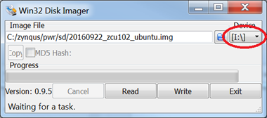 |
| Win32 Disk Imager.png |
Figure 3. Win32 Disk Imager.
- C:/<PATH TO SD-CARD IMAGE>/20180418_zcu102_ultra96_aicdemo.img
- Be extremely careful to select the Device Letter of your SD card (whatever drive selected will be overwritten), then select “Write”.
- When programming has completed, insert this SD card into the Xilinx Evaluation Board (e.g. ZCU102) and power cycle the evaluation board. In a minute, you should see the Ubuntu desktop on the DisplayPort monitor for Ubuntu SD images, or you should see a Linux prompt for all other Linux SD images. If you do not, please see Common Setup Issues below.
After the Image is written, navigate to the boot partition. There are two subfolders zcu102_boot and ultra96_boot. Copy one set of boot files (according to your board) into the base of the boot partition.
4.3 Board Setup
This section describes how to set up the board.
ZCU102:
Connect the monitor to the board via Display Port cable. Then plug the mouse, keyboard and webcam into the USB 3.0 hub and connect the hub to the board via USB3 micro-B adapter. Optionally connect the UART interface to your laptop using the micro USB cable, to be able to run a terminal emulator. Details on how to bring up the serial console can be found in section Start Serial Console. Furthermore please make sure, that all jumpers and switches on the board are as described in section Jumper and Switch Settings.
After all this is done, connect the board to power supply, insert the SD-Card and turn the board on. Within one minute Petalinux with Ubuntu Desktop should boot. There will be an aic/ folder and an init.sh script in /root. Please run ./init.sh to bring up the Ethernet connection and to compile a required library (libsds).
Ultra96:
Connect the monitor to the board via Mini Display port cable. Then plug the mouse, keyboard and webcam into the USB 3.0 hub and connect the hub to the board via USB. Optionally connect the UART interface to your laptop using the micro USB cable, to be able to run a terminal emulator. Details on how to bring up the serial console can be found in section Start Serial Console. Furthermore please make sure, that all jumpers and switches on the board are as described in section Jumper and Switch Settings.
After all this is done, please connect the board to power supply, insert the SD-Card and turn the board on. Within one minute Petalinux with Ubuntu Desktop should boot.
4.3.1 Start Serial Console
The following settings are required for a terminal emulator:
• Baud Rate: 115200
• Data: 8 bit
• Parity: None
• Stop: 1 bit
• Flow Control: None
4.3.2 Jumper and Switch Settings
Ultra96
Set boot mode to SD card:
• SW2[1:2] - off, on
ZCU102
Set boot mode to SD card1 : * Rev 1.0: SW6[1:4] - on, off,off,off * Rev D2: SW6[1:4] - off, on, off, on
Configure USB jumpers for host mode * J110: 2-3 * J109: 1-2 * J112: 2-3 * J7: 1-2 * J113: 1-2.
All other jumpers should be at the factory default settings
4.4 Run the design
There are four available configurations of the application:
- 4K resolution, BNN in SW
- 4K resolution, BNN in HW
- HD resolution, BNN in SW
- HD resolution, BNN in HW
For each configuration one can find a Desktop icon, with which one can start the application. Fig. 4.1 shows the relevant Buttons in the GUI. Before the BNN can classify anything, a source of images needs to be determined. For this you can choose between using a dataset represented by a folder full of images (in *.jpg, *.png or *ppm format) by clicking the icon with the 4 blueish squares (highlighted in dark blue in Fig. 4.1) right below the menu tab; or use an attached webcam by clicking on the dark green highlighted camera icon right next to the data set icon.
 |
| Fig. 4.1 Control elements |
When using the dataset as source the default path is pre-set to /root/neuralnet/images/. If you have a different dataset then select the path to the image set. This can be done by clicking on the menu tab and then choose settings. In the case of choosing the camera as a source, a prompt to choose the camera will pop up right after clicking on the camera icon. The software will check for the first 10 possible existing cameras and highlight those which are actually connected.
Once an input source has been selected, the classification can be controlled by the three buttons highlighted in yellow in Fig. 4.1. Clicking the play button results in continuously loading and classifying images. In dataset mode this means that the software goes through the folder and loads one image after another to the BNN. When reaching the last image, it will restart with the first one. Clicking the Pause button will stop this process. The forward button loads a single image into the BNN and stops after it has been classified.
5. Expected Results
Ultra96:
Tiles per second: ~14500
Images per second: ~66
Acceleration: ~6200
ZCU102:
Tiles per second: ~19500
Images per second: ~90
Acceleration: ~8500
6. Rebuilding the Design from sources
6.1 Requirements
• Xilinx Licenses for Vivado 2017.3
• Xilinx Tool Installations for Vivado + Vivado HLS version 2017.3 and Petalinux tool version 2017.3
• SD card with at least 8GB (16GB recommended)
6.2 Supported platforms
• ZCU102 production silicon
• Ultra96 production silicon
6.3 Rebuild FPGA Design
The block diagram of the design can be seen below:
 |
| Fig. 6.1 Block Diagram for ZCU102 |
 |
| Fig. 6.2 Block Diagram for Ultra96 |
BlackBoxJam_0 is the IP core containing the Binary Neural Networks and the weights.
To rebuild this Vivado project, please execute the following steps:
- Make sure you are in a Xilinx 2017.3 environment on a linux machine/server
- Go into the folder aic/ of the source files and export the variable XILAIC_ROOT (export XI-LAIC_ROOT=$(pwd))
- Go into the folder scripts/ and run make-hw.sh a <platform name> to build the HLS project and the Vivado project.
The make-hw.sh script has different build options:
a builds the HLS and Vivado Project
h builds only the HLS project
b builds the Vivado project including the bitstream
The platform name can be either zcu102 or ultra96.
The ouput can be found in aic/output/hls_syn and aic/output/vivado.
6.4 Rebuild Petalinux project
We are using all PetaLinux build elements (FSBL, PMU firmware, ARM Trusted Firmware, U-Boot,
device tree, kernel image) except the root filesystem; instead the Ubuntu-based root file system of
the Zynq UltraScale+ MPSoC Base TRD will be used.
- Make sure you are in a Vivado 2017.3 and a PetaLinux 2017.3 environment.
- Change into the directory src_sw/<platform name>-petalinux/.
- Import the hardware definition file of your FPGA design by executing: petalinux-config --get-hw-description ../../output/vivado/<platform name>/<platform name>.sdk
- Build the PetaLinux project by executing: make build
- Package the BOOT.BIN file by executing: make package-boot
The output files BOOT.BIN and image.ub can be found in src_sw/<platform name>-petalinux/images/linux.
6.5 Prepare the SD-Card
- Take the SD card image provided by MLE and burn it onto your SD card. The SD card should now have two partitions, one small one formatted with FAT32 containing a BOOT.BIN and image.ub and one large one containing a root file system.
- Copy the BOOT.BIN and image.ub file in src_sw/<platform name>-petalinux/images/linux to the first partition of the SD card.
6.6 Bring up the board
Bring up the board and the design as described in section Bing up the system and run the design.
6.7 Install necessary packages and configuration (OpenCV & QT & libsds)
All these scripts and actions have to be done on your hardware board.
OpenCV
In order to run the GUIi, OpenCV-3.3.0 and QT are required. The script aic/scripts/install_opencv.sh updates your linux and required packages and finally installs OpenCV locally to your root folder. Ideally the path should match the one in aic/src_sw/xlx_aic_gui/xlx_aic_gui.pro.
QT
In case the Demo shall run on the board, QT needs to be installed with the mali driver. For that get the sources from qt-everywhere-opensource-src-5.4.2.zip. (Link: Xilinx Wiki MALI driver and Zynq Qt and Qwt Base Libraries-Build Instructions)
Unpack the zip and fix the configure_mali.sh script as follows:
line 3: function usage { --> usage () {
line 38: if ( ... == ... ) --> if ( ... = ... )
Furthermore the following adjustments need to be made: Replace the “-no-xcb “ flag with “-xcb”.
- Replace the “-no-xcb” flga with “-xcb”
- Add a new flag “-egl .
- Add a new flag “-no-kms”.
- Add a new flag “-qt-xcb”.
- Replace the “-eglfs” flag with “-no-eglfs”.
- Replace the flag “-no-xcb-xlib” with “-xcb-xlib”
After saving the script you need to set the following environment variables.
If you cross compile:
- export QT_MALI_LIB = <petalinux project directory>/build/tmp/sysroots/plnx_aarch64/usr/lib
- export QT_MALI_INCLUDE = <petalinux project directory>/build/tmp/sysroots/plnx_aarch64/usr/include
If you compile on the board
- export QT_MALI_LIB = /usr/lib
- export QT_MALI_INCLUDE = /usr/include
Then run the following commands to compile the QT source with X11 support. Few errors will arisewhile compiling and which are ignorable.
./configure_mali.sh aarch64 -p <QT Installation_directory>
make
After successful compilation of QT source code, run the below command to install the QT at specified installation directory.
make install
libsds
To recompile the sds library, go to aic/src_hw/libsds and run:
make
6.8 To build and run the application
To build a configuration, go to the folder aic/src_sw/xlx_aic_gui, and run the script build.sh. Please choose the correct option corresponding to your desired configuration and run the
script with this option. The script compiles the application and creates a Desktop icon, with which one can start the application.
To compile and run an application based on qmake, you have to set the following QT environment
variables. Best way to do this, is the /root/.bashrc file.
export QT_QPA_FONTDIR=/usr/local/lib/fonts
export QT_QPA_PLATFORM_PLUGIN_PATH=/usr/local/plugins
export QML2_IMPORT_PATH=/usr/local/qml
export QT_QPA_EGLFS_PHYSICAL_WIDTH=1000
export QT_QPA_EGLFS_PHYSICAL_HEIGHT=1000
export QT_QPA_PLATFORM=xcb
export LD_LIBRARY_PATH=/root/etc/x11_mali:$LD_LIBRARY_PATH
export MALI_SINGLEBUFFER=0
export LD_LIBRARY_PATH=/root/opencv-3.3.0/lib:$LD_LIBRARY_PATH
export HOME=/root
To compile the application, two steps have to be done in general: Run qmake to generate a Makefile for the application. Run make to compile the application and generate an executable. In our case, there exists an build.sh script in /root/aic/src_sw/xlx_aic_gui to compile the program.
6.9 Load different weights into the BNN
Take the weights of your trained network in binary format and put them to:
aic/src_hw/bnn-pynq-mpsoc/params/
Then modify the file
aic/src_sw/xlx_aic_proc/inc/xilaic_config.h
to contain the correct path to your new weights. After that, please rebuild the hardware as described in Rebuild FPGA Design. If the path to the weights is not given correctly, the application will throw a ‘const char-exeption’ during execution.