This page provides all the information related to VCU HDMI ROI TRD design for ZCU106.
Table of Contents
1 Overview
The primary goal of this VCU ROI design is to demonstrate the use of DPU (Deep learning Processor Unit) block for extracting the ROI (Region of Interest) from input video frames and to use this information to perform ROI based encoding using VCU (Video Codec Unit) encoder hard block present in Zynq UltraScale+ EV devices.
The design will serve as a platform to accelerate Deep Neural Network inference algorithms using DPU and demonstrate the ROI feature of VCU encoder. The design uses a Deep Convolutional Neural Network (CNN) named Densebox, running on DPU to extract ROI Information (e.g. ‘face’ in this case).
The Design will use Vivado IPI flow for building the hardware platform and Xilinx Yocto Petalinux flow for software design. It will use Xilinx IP and Software driver to demonstrate the capabilities of different components.
The Vitis platform will be created from the Vivado/PetaLInux build artifacts, and then using the Vitis acceleration flow will be used to insert the DPU into the platform to create the final bitstream.
The following figure shows one of the use cases (Serial pipeline) with face detection with enhanced ROI on ZCU106.

Serial: Face detection with enhanced ROI on ZCU106.
The following figure shows one of the use cases (streaming pipeline) with face detection with enhanced ROI on ZCU106.
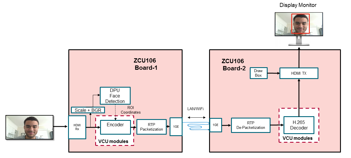
Streaming: Face detection with enhanced ROI on ZCU106.
1.1 System Architecture
The following figure shows the block diagram of the ROI design
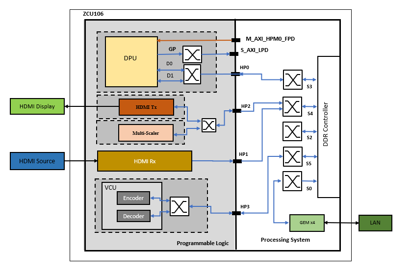
1.2 Hardware Architecture
This section gives a detailed description of the blocks used in the hardware design. The functional block diagram of the design is shown in the below figure.
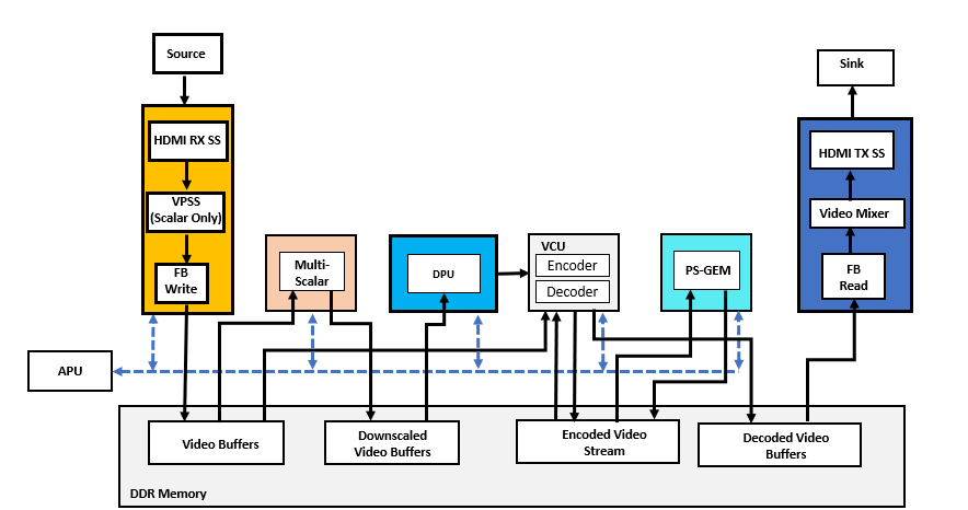
There are seven primary Sections in the design.
HDMI Capture Pipeline:
Captures video frame buffers from Capture source in 4K Resolution, NV12 Format
Writes the buffers into DDR Memory with Frame Buffer Write IP
Multi-scaler Block:
Reads the Video Buffers from DDR Memory
Scales down the buffer to the 640x360 size (suitable for dpu)
Converts the format from NV12 to BGR
Writes the Down-scaled buffer to DDR Memory
DPU Block:
Reads the downscaled buffers from DDR Memory
Runs the Densebox algorithm to generate the ROI information for each frame buffer
Passes the ROI information to VCU Encoder
VCU Encoder:
Reads the 4K NV12 Buffer from DDR Memory
Receives the ROI metadata from DPU IP
Encodes the video buffers based on the ROI Information
Finally writes the encoded stream to DDR Memory
PS GEM:
Reads the Encoder stream from DDR Memory
Streams out the encoded stream via Ethernet
VCU Decoder:
Decodes the received encoded frame and writes to memory
HDMI-Tx:
Displays the decoded frames on HDMI Display
This design supports the following video interfaces:
Sources |
|
|---|---|
Sinks |
|
VCU Codec |
|
DPU | |
Streaming Interfaces | 1G Ethernet PS GEM |
Video Format | NV12 |
Supported Resolution | 4Kp30 |
1.3 VCU ROI Software
1.3.1 GStreamer Pipeline
The GStreamer plugin demonstrates the DPU capabilities with Xilinx VCU encoder’s ROI(Region of Interest) feature. The plugin will detect ROI (i.e. face co-ordinates) from input frames using DPU IP and pass the detected ROI information to the Xilinx VCU encoder. The following figure shows the data flow for GStreamer pipeline of stream-out use case.

Block Diagram of Stream-out Pipeline
fd = v4l2 frame data, fd' = DPU compatible frame data
As shown in the above figure, the stream-out GStreamer pipeline performs the below list of operations:
v4l2src captures the data from HDMI-Rx in NV12 format and pass to xlnxroivideo1detect GStreamer plugin
xlnxroivideo1detect GStreamer plugin will scale down to 640x360 resolution and convert the data into BGR format
640x360 BGR frame will be provided to DPU IP as an input to find ROI (i.e. face co-ordinates)
Extracted ROI information will be passed to VCU encoder
The encoder will encode the input data by encoding ROI regions with high quality as compared to non-ROI region using received ROI information
Stream-out the encoded data using RTP protocol
The following figure shows the data flow for the GStreamer pipeline of stream-in use cases.

Block Diagram of Stream-in Pipeline
fd = Gst-Omx Frame data
As shown in the above figure, the stream-in GStreamer pipeline performs the below list of operations:
Stream-in the encoded data using RTP protocol
The Xilinx VCU decoder will decode the data
Display the decoded data on HDMI-Tx display
The below figure shows the xlnxroivideo1detect GStreamer plugin data flow.
As shown in the above figure, our xlnxroivideo1detect GStreamer plugin will perform below the list of operations:
DPU is initialized
DPU GStreamer plugin receives the data frame from HDMI-Rx through a v4l2src plugin
Create the DPU task
Scale the input frame to 640x360 resolution using Xilinx Scaler IP
Convert the input frame data format from NV12 to BGR format using Xilinx Color Space Converter(CSC) soft IP
Prepare the OpenCV image using BGR data
Pass the intermediate OpenCV image to the DPU
Run the DPU task
Extract the ROI(face) co-ordinates from the DPU output
Map the detected face co-ordinates to the original input frame resolution
Fill the ROI metadata buffer using extracted ROI (face) co-ordinates
Pass the ROI metadata buffer and input NV12 frame data buffer to the Xilinx VCU encoder
De-initialize the DPU task
1.3.2 DPU(Deep Learning Processor Unit)
DPU is a programmable engine optimized for deep neural networks. It is a group of parameterizable IP cores pre-implemented on the hardware with no place and route required. The DPU is released with the Vitis AI specialized instruction set, allowing efficient implementation of many deep learning networks.
Refer to DPU IP PG338 and UG1354 to know more details on DPU.
The following figure shows the DPU Top-Level Block Diagram.
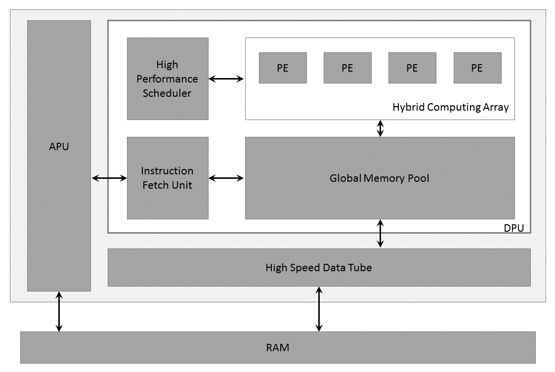
DPU Top-level Block Diagram
The DPU IP can be implemented in the programmable logic (PL) of the selected Zynq® UltraScale+™ MPSoC device with direct connections to the processing system (PS). The DPU requires instructions to implement a neural network and accessible memory locations for input images as well as temporary and output data. A program running on the application processing unit (APU) is also required to service interrupts and coordinate data transfers.
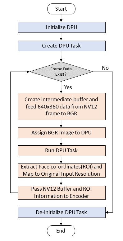
The following figure shows the sequence of operations performed on the DPU device.
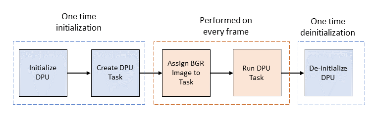
The following sequence of steps are performed to access and run face detection using the DPU device:
DPU device is initialized
Instantiate a DPU Task from DPU Kernel and allocate corresponding DPU memory buffer
Set the input image to created DPU task
Run the DPU task to find the faces from the input image
DPU device is uninitialized
1.4 Software Tools and System Requirements
Hardware
Required:
ZCU106 evaluation board (rev C/D/E/F/1.0) with power cable
Monitor with HDMI input supporting 3840x2160 resolution or 1920x1080 resolution
HDMI cable 2.0 certified
Class-10 SD card
Ethernet cable
Optional:
USB pen drive formatted with the FAT32 file system and hub
SATA drive formatted with the FAT32 file system, external power supply, and data cable
Software Tools
Required:
Linux host machine for all tool flow tutorials (see UG1144 for detailed OS requirements)
PetaLinux Tools version 2020.2 (see UG1144 for installation instructions)
Git a distributed version control system
Serial terminal emulator e.g. teraterm
Download, Installation, and Licensing of Vivado Design Suite 2020.2
The Vivado Design Suite User Guide explains how to download and install the Vivado® Design Suite tools, which include the Vivado Integrated Design Environment (IDE), High-Level Synthesis tool, and System Generator for DSP. This guide also provides information about licensing and administering evaluation and full copies of Xilinx design tools and intellectual property (IP) products. The Vivado Design Suite can be downloaded from here.
LogiCORE IP Licensing
The following IP cores require a license to build the design.
Video Mixer- Included with Vivado - PG243
Video PHY Controller - Included with Vivado - PG203
HDMI-Rx/Tx Subsystem - Purchase license (Hardware evaluation available) - PG235 & PG236
Video Processing Subsystem (VPSS) - Included with Vivado - PG231
To obtain the LogiCORE IP license, please visit the respective IP product page and get the license.
AR# 44029 - Licensing - LogiCORE IP Core licensing questions
Compatibility
The reference design has been tested successfully with the following user-supplied components.
HDMI Monitor:
Make/Model | Resolutions |
|---|---|
LG 27UD88 | 3840 x 2160 @ 30Hz |
Samsung LU28ES90DS/XL | 3840 x 2160 @ 30Hz |
Cable:
HDMI 2.0 compatible cable
The below table provides the performance information:
Resolution | FPS Achieved |
|---|---|
4Kp30 | 27 - 30 |
1080p30 | 30 |
Above FPS are measured withgop-mode=basic gop-length=60 b-frames=0 target-bitrate=1500 num-slices=8 control-rate=constant prefetch-buffer=true low-bandwidth=false qp-mode=roi encoder parameters for AVC and HEVC.
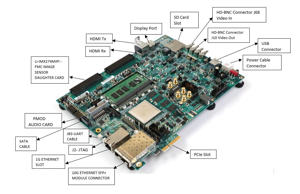
1.5 Board Setup
The below section will provide the information on the ZCU106 board setup for running ROI design.
Connect the Micro USB cable into the ZCU106 Board Micro USB port J83, and the other end into an open USB port on the host PC. This cable is used for UART over USB communication.
Insert the SD card with the images copied into the SD card slot J100. Please find here how to prepare the SD card for a specific design.
Set the SW6 switches as shown in the below Figure. This configures the boot settings to boot from SD.

Connect 12V Power to the ZCU106 6-Pin Molex connector
Connect one end of HDMI cable to the board’s P7 stacked HDMI connector (lower port) and another end to HDMI source
Connect one end of HDMI cable to the board’s P7 stacked HDMI connector (upper port) and another end to the HDMI monitor
For a USB storage device, connect the USB hub along with the mouse. (Optional)
For SATA storage device, connect SATA data cable to SATA 3.0 port. (Optional)
Set up a terminal session between a PC COM port and the serial port on the evaluation board (See the Determine which COM to use to access the USB serial port on the ZCU106 board for more details).
Copy the VCU-HDMI-ROI images into the SD card and insert the SD card on the board
The below images will show how to connect interfaces on the ZCU106 board
1.6 Run Flow
The VCU ROI TRD package is released with the source code, Vivado project, Petalinux BSP, and SD card image that enables the user to run the demonstration. It also includes the binaries necessary to configure and boot the ZCU106 board. Prior to running the steps mentioned in this wiki page, download the VCU ROI TRD package and extract its contents to a directory referred to as TRD_HOME which is the home directory.
Refer below link to download the VCU HDMI ROI TRD package.
TRD package contents are placed in the following directory structure.
rdf0617-zcu106_vcu_hdmi_roi_2020_2
├── apu
│   └── vcu_petalinux_bsp
│       └── xilinx-vcu-roi-zcu106-v2020.2-final.bsp
├── dpu
│   ├── 0001-Added-ZCU106-configuration-to-support-DPU-in-ZCU106.patch
│   ├── dpu_conf.vh
│   └── vitis_platform
│       └── zcu106_dpu
├── image
│   ├── bootfiles
│   │   ├── bl31.elf
│   │   ├── linux.bif
│   │   ├── pmufw.elf
│   │   ├── system.bit
│   │   ├── system.dtb
│   │   ├── u-boot.elf
│   │   └── zynqmp_fsbl.elf
│   ├── README.txt
│   ├── sd_card
│   │   ├── boot
│   │   └── root
│   └── sd_card.img
└── pl
    ├── constrs
    │   └── vcu_roi.xdc
    ├── designs
    │   └── zcu106_ROI_HDMI
    ├── prebuild
    │   └── zcu106_ROI_HDMI.xsa
    ├── README.md
    └── srcs
        ├── hdl
        └── ip
The below snippet shows the directory structure of various configuration files which are useful for vcu_gst_app to run Display, and Streaming use cases. All these configurations files are placed in the TRD_HOME/image/sd_card/boot/config directory.
├── image
  └──sd_card
    └──boot
      └── config
        ├── 1080p30
        │   ├── Display
        │   ├── Stream-in
        │   └── Stream-out
        ├── 4kp30
        │   ├── Display
        │   ├── Stream-in
        │   └── Stream-out
        └── input.cfg
1.6.1 Preparing the SD card
There are three ways to prepare the SD card for booting. Each method is detailed below.
Using ready to test image
Flash SD Card with
sd_card.imgusing Etcher or Win32DiskImagerBoot the board with Flashed SD Card
sd_card.imgis available atrdf0617-zcu106_vcu_hdmi_roi_2020_2/image/sd_card.imgAll the required Vitis packages are already installed in ready to test
rdf0617-zcu106_vcu_hdmi_roi_2020_2/image/sd_card.img
Using Pre-built images
To Create SD Card with two partitions: Boot(FAT32+Bootable) and Root(EXT4) Refer this Link.
Copy
bootcontent fromrdf0617-zcu106_vcu_hdmi_roi_2020_2/image/bootto Boot partition in SD CardExtract
rootfs.ext4fromrdf0617-zcu106_vcu_hdmi_roi_2020_2/image/rootto Root partition in SD Card usingBoot the board with Flashed SD Card
Use the Output of the Build Flow
To Create SD Card with two partitions: Boot(FAT32+Bootable) and Root(EXT4) Refer this Link.
For Build Flow refer this steps and copy mentioned generated dpu build images
bd.hwh BOOT.BIN boot.scr dpu.xclbin Image system.dtbinto BOOT partition of the SD card and extract generatedrootfs.ext4into ROOT partition of SD CardCopy the mentioned
bootcontentconfig, vitis, autostart.sh, setup.shfromrdf0617-zcu106_vcu_hdmi_roi_2020_2/image/boot/directory to Boot partition in SD CardBoot the board with Flashed SD Card
All the required Vitis AI packages are already available in
rdf0617-zcu106_vcu_hdmi_roi_2020_2/image/boot/vitisdirectory which are installed automatically during 1st time boot. Please wait till target setup complete and Vitis AI packages are installed.
1.6.2 Using GStreamer Application (vcu_gst_app)
The vcu_gst_app is a command-line multi-threaded Linux application. The command-line application requires an input configuration file (input.cfg) to be provided in the plain text.
Before Running vcu_gst_app pipelines run below modetest commands to set CRTC configurations.
modetest -D a00c0000.v_mix -s 40:3840x2160-30@AR24 -w 36:"alpha":0 &
modetest -D a00c0000.v_mix -s 40:3840x2160-30@AR24
Display: Capture → (ROI) → Encode → Decode → Display
4Kp30 HEVC Display Pipeline execution using
vcu_gst_appvcu_gst_app /media/card/config/4kp30/Display/Single_4kp30_HEVC.cfg
Stream-out: ( Server )
Set IP address for server:
ifconfig eth0 192.168.25.90
4Kp30 HEVC Stream-out Pipeline execution using
vcu_gst_appvcu_gst_app /media/card/config/4kp30/Stream-out/Single_4kp30_HEVC.cfg
Stream-in: ( Client )
Set IP address for the client:
ifconfig eth0 192.168.25.89
4Kp30 HEVC Stream-in Pipeline execution using
vcu_gst_appvcu_gst_app /media/card/config/4kp30/Stream-in/input.cfg
1.6.3 GStreamer Pipelines using mediasrcbin plugin
This section covers the GSreamer pipelines using mediasrcbin plugin for serial and streaming ROI use-cases. This mediasrcbin plugin is Xilinx specific plugin which is a bin element on top of v4l2src. It parses and configures the media graph of a media device automatically.
Before Running Gstremer pipelines run below modetest commands to set CRTC configurations.
modetest -D a00c0000.v_mix -s 40:3840x2160-30@AR24 -w 36:"alpha":0 &
modetest -D a00c0000.v_mix -s 40:3840x2160-30@AR24
Serial: Capture → (ROI) → Encode → Decode → Display
Run the following
gst-launch-1.0command for serial pipeline (capture → roi_plugin → encode → decode → display)Serial Pipeline
gst-launch-1.0 mediasrcbin media-device=/dev/media0 v4l2src0::io-mode=4 ! video/x-raw, width=3840, height=2160, format=NV12, framerate=30/1 ! xlnxroivideo1detect capture-io-mode=4 output-io-mode=5 relative-qp=-21 ! omxh265enc gop-mode=basic gop-length=60 b-frames=0 target-bitrate=1500 num-slices=8 control-rate=constant prefetch-buffer=true low-bandwidth=false filler-data=true cpb-size=1000 initial-delay=500 qp-mode=roi ! video/x-h265, profile=main, alignment=au ! queue ! omxh265dec internal-entropy-buffers=5 low-latency=0 split-input=true ! queue max-size-bytes=0 ! fpsdisplaysink name=fpssink text-overlay=false 'video-sink=kmssink bus-id=a00c0000.v_mix hold-extra-sample=1 show-preroll=false sync=true' sync=true -v
Stream-out ( Server ): Capture → (ROI) → Encode → Stream-out
Set IP address for server:
ifconfig eth0 192.168.25.90
Run the following
gst-launch-1.0command for stream-out pipelineStream-out Pipeline
gst-launch-1.0 mediasrcbin media-device=/dev/media0 v4l2src0::io-mode=4 ! video/x-raw, format=NV12, width=3840, height=2160, framerate=30/1 ! xlnxroivideo1detect capture-io-mode=4 output-io-mode=5 relative-qp=-21 ! omxh265enc gop-mode=basic gop-length=60 b-frames=0 target-bitrate=1500 num-slices=8 control-rate=constant prefetch-buffer=true low-bandwidth=false filler-data=true cpb-size=1000 initial-delay=500 periodicity-idr=60 qp-mode=roi ! video/x-h265, profile=main, alignment=au ! queue ! mpegtsmux alignment=7 name=mux ! rtpmp2tpay ! udpsink host=192.168.25.89 port=5004
Here
192.168.25.89is host/client IP address and5004is port no.Make sure HDMI-Rx source should be configured to 4Kp30 mode
Stream-in ( Client ): Stream-in→ Decode → Display
Set IP address for the client:
ifconfig eth0 192.168.25.89
Run the following
gst-launch-1.0command for stream-in pipeline where5004is port numberStream-in Pipeline
gst-launch-1.0 udpsrc port=5004 buffer-size=60000000 caps="application/x-rtp, clock-rate=90000" ! rtpjitterbuffer latency=1000 ! rtpmp2tdepay ! tsparse ! video/mpegts ! tsdemux name=demux ! queue ! h265parse ! video/x-h265, profile=main, alignment=au ! omxh265dec internal-entropy-buffers=5 low-latency=0 split-input=true ! queue max-size-bytes=0 ! fpsdisplaysink name=fpssink text-overlay=false 'video-sink=kmssink bus-id=a00c0000.v_mix hold-extra-sample=1 show-preroll=false sync=true' sync=true -v
For all 1080p30 commands replace width from 3840 to 1920 and height from 2160 to 1080
1.6.4 GStreamer Pipelines using v4l2src plugin
This section covers the GSreamer pipelines using v4l2src plugin for serial and streaming ROI use-cases. Before Running Gstremer pipelines run modetest command for HDMI-Tx and media-ctl command for HDMI-Rx as mentioned below.
Before Running Gstremer pipelines run below modetest commands to set CRTC configurations.
modetest -D a00c0000.v_mix -s 40:3840x2160-30@AR24 -w 36:"alpha":0 &
modetest -D a00c0000.v_mix -s 40:3840x2160-30@AR24
Run below media-ctl commands to set scaler configuration when HDMI Input Source is configured for 4Kp30 resolution and RBG888_1x24 color format.
media-ctl -d /dev/media0 -V "\"a0040000.v_proc_ss\":0 [fmt:RBG888_1X24/3840x2160 field:none]"
media-ctl -d /dev/media0 -V "\"a0040000.v_proc_ss\":1 [fmt:VYYUYY8_1X24/3840x2160 field:none]"
Make sure HDMI-Rx is configured for 4Kp resolution and RBG888_1x24 color format
v_proc_ss:0 should match the HDMI-Rx input source resolution and color format, and that the v_proc_ss:1 should match the Gstremer Pipeline resolution and color format
Serial: Capture → (ROI) → Encode → Decode → Display
Run the following
gst-launch-1.0command for serial pipeline (capture → roi_plugin → encode → decode → display)Serial Pipeline
gst-launch-1.0 v4l2src device=/dev/video0 io-mode=4 ! video/x-raw, width=3840, height=2160, format=NV12, framerate=30/1 ! xlnxroivideo1detect capture-io-mode=4 output-io-mode=5 relative-qp=-21 ! omxh265enc gop-mode=basic gop-length=60 b-frames=0 target-bitrate=1500 num-slices=8 control-rate=constant prefetch-buffer=true low-bandwidth=false filler-data=true cpb-size=1000 initial-delay=500 qp-mode=roi ! video/x-h265, profile=main, alignment=au ! queue ! omxh265dec internal-entropy-buffers=5 low-latency=0 split-input=true ! queue max-size-bytes=0 ! fpsdisplaysink name=fpssink text-overlay=false 'video-sink=kmssink bus-id=a00c0000.v_mix hold-extra-sample=1 show-preroll=false sync=true' sync=true -v
Stream-out ( Server ): Capture → (ROI) → Encode → Stream-out
Set IP address for server:
ifconfig eth0 192.168.25.90
Run the following
gst-launch-1.0command for stream-out pipelineStream-out Pipeline
gst-launch-1.0 v4l2src device=/dev/video0 io-mode=4 ! video/x-raw, format=NV12, width=3840, height=2160, framerate=30/1 ! xlnxroivideo1detect capture-io-mode=4 output-io-mode=5 relative-qp=-21 ! omxh265enc gop-mode=basic gop-length=60 b-frames=0 target-bitrate=1500 num-slices=8 control-rate=constant prefetch-buffer=true low-bandwidth=false filler-data=true cpb-size=1000 initial-delay=500 periodicity-idr=60 qp-mode=roi ! video/x-h265, profile=main, alignment=au ! queue ! mpegtsmux alignment=7 name=mux ! rtpmp2tpay ! udpsink host=192.168.25.89 port=5004
Here
192.168.25.89is host/client IP address and5004is port no.Make sure HDMI-Rx source should be configured to 4Kp30 mode
Stream-in ( Client ): Stream-in→ Decode → Display
Set IP address for the client:
ifconfig eth0 192.168.25.89
Run the following
gst-launch-1.0command for stream-in pipeline where5004is port numberStream-in Pipeline
gst-launch-1.0 udpsrc port=5004 buffer-size=60000000 caps="application/x-rtp, clock-rate=90000" ! rtpjitterbuffer latency=1000 ! rtpmp2tdepay ! tsparse ! video/mpegts ! tsdemux name=demux ! queue ! h265parse ! video/x-h265, profile=main, alignment=au ! omxh265dec internal-entropy-buffers=5 low-latency=0 split-input=true ! queue max-size-bytes=0 ! fpsdisplaysink name=fpssink text-overlay=false 'video-sink=kmssink bus-id=a00c0000.v_mix hold-extra-sample=1 show-preroll=false sync=true' sync=true -v
For all 1080p30 commands replace width from 3840 to 1920 and height from 2160 to 1080
1.7 Build Flow
Refer below link to download the VCU HDMI ROI TRD package.
Unzip the released package.
unzip </path/to/downloaded/zipfile>/rdf0617-zcu106_vcu_hdmi_roi_2020_2.zip
The following tutorials assume that the $TRD_HOME environment variable is set as given below.
export TRD_HOME=</path/to/downloaded/zipfile>/rdf0617-zcu106_vcu_hdmi_roi_2020_2
1.7.1 Hardware Build Flow
This section explains the steps to build the hardware platform and generate XSA using the Vivado tool.
Refer to the Vivado Design Suite User Guide: Using the Vivado IDE, UG893, for setting up the Vivado environment.
Refer to the vivado-release-notes-install-license(UG973) for installation.
Make sure that the necessary IP licenses are in place
On Linux:
Open a Linux terminal
Change directory to
$TRD_HOME/plfolderSource Vivado
settings.shbash source <path/to/Vivado-installer>/tool/Vivado/2020.2/settings64.sh
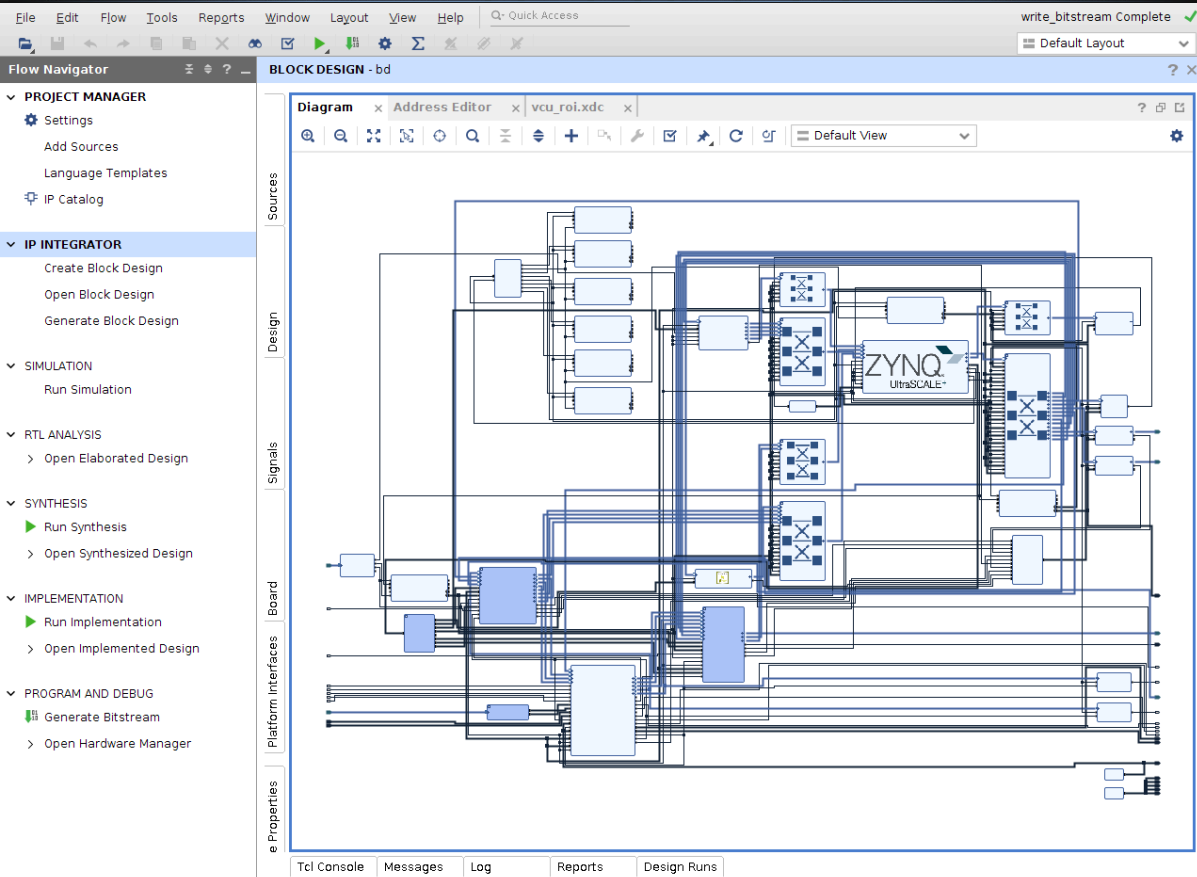
Run the following command to create the Vivado IPI project and invoke the GUI and generate XSA required for the platform
vivado -source ./designs/zcu106_ROI_HDMI/project.tcl
The project.tcl script does the following
Creates project
Creates IPI Block design with platform interfaces
Runs Synthesis and Implementation
Builds bitstream with no accelerators
Export the HW to XSA
zcu106_ROI_HDMI_wrapper.xsa is created
stored in the directory ../zcu106_ROI_HDMI.xsa/
at location
TRD_HOME/pl/build/zcu106_ROI_HDMI/zcu106_ROI_HDMI.xsa/This XSA is used by Petalinux for platform creation and also by the Vitis Tool for DPU Kernel Integration.
After executing the script, the Vivado IPI block design comes up as shown in the below figure.
1.7.1.1 Platform Interfaces
The screenshots below show the platform interfaces that have been made available to the Vitis tool for linking in acceleration IP.
In the case of this reference design, the DPU Kernel will be inserted.
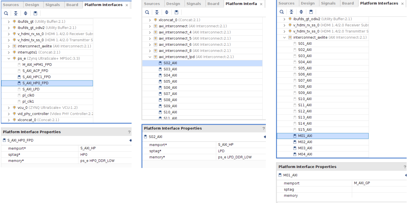
After the DPU Kernel is integrated dynamically with the platform using Vitis Flow, the connections are as shown below
The DPU Data ports are connected to the HP0 Port(S_AXI_HP0_FPD) of PS .
The DPU Instruction port is connected to the S_AXI_LPD port of PS through axi_interconnect_lpd
The DPU S_AXI_Control port is connected to the M_AXI_HPM0_LPD port of PS through interconnect_axilite
The DPU interrupt is connected to the axi interrupt controller dynamically
1.7.2 Petalinux build Flow
This tutorial shows how to build the Linux image and boot image using the PetaLinux build tool.
PetaLinux Installation: Refer to the PetaLinux Tools Documentation (UG1144) for installation.
It is recommended to follow the build steps in sequence
Source Petalinux
settings.shbash source <path/to/petalinux-installer>/tool/petalinux-v2020.2-final/settings.sh
Create PetaLinux project
cd $TRD_HOME/apu/vcu_petalinux_bsp
petalinux-create -t project -s xilinx-vcu-roi-zcu106-v2020.2-final.bsp
Configure the PetaLinux project
cd xilinx-vcu-roi-zcu106-v2020.2-final
petalinux-config --silentconfig --get-hw-description=<Path to directory of XSA>
For e.g.
using the prebuild XSA
petalinux-config --silentconfig --get-hw-description=$TRD_HOME/pl/prebuild/
using the XSA generated by running the Hardware
project.tclscriptspetalinux-config --silentconfig --get-hw-description=$TRD_HOME/pl/build/zcu106_ROI_HDMI/zcu106_ROI_HDMI.xsa/
zcu106_ROI_HDMI_wrapper.xsais available in directory zcu106_ROI_HDMI.xsa
Build the PetaLinux project
petalinux-build
1.7.3 Prepare Build Artifacts for Platform Creation
To prepare artifacts required for ZCU106 Vitis platform creation, follow below steps after petalinux build
Go to the petalinux build image directory
cd $TRD_HOME/apu/vcu_petalinux_bsp/xilinx-vcu-roi-zcu106-v2020.2-final/images/linux
Create
linux.biffile as below inimages/linuxdirectory.linux.biffile is required to create ZCU106 Vitis platform which has information related to boot components. After zcu106 vitis platform creation thislinux.biffile will be part of platform, which is required to build DPU and generate finalBOOT.bin/* linux */ the_ROM_image: { [bootloader, destination_cpu = a53-0] <zynqmp_fsbl.elf> [pmufw_image] <pmufw.elf> [destination_device=pl] <bitstream> [destination_cpu=a53-0, exception_level=el-3, trustzone] <bl31.elf> [destination_cpu=a53-0, exception_level=el-2] <u-boot.elf> }Copy generated images into boot and image directory by following below commands. Use created
linux.bifto copy into boot directory.mkdir boot mkdir image cp linux.bif boot/. cp bl31.elf pmufw.elf u-boot.elf zynqmp_fsbl.elf boot/. cp boot.scr Image system.dtb image/.
1.7.4 ZCU106 Platform Creation
This section shows how to create a Vitis acceleration platform for the zcu106 using the Vitis IDE.
Ready to use vitis platform is available at
TRD_HOME/dpu/vitis_platform/zcu106_dpuIt is recommended to follow the build steps in sequence
source <vitis install path>/Vitis/2020.2/settings64.sh
vitis &
Choose project workspace and click on Launch to begin

User can create Workspace in any directory. For example $TRD_HOME/vitis_workspace
Launch the New Platform Project dialog box using following step:
Go to File > New > Platform Project

Provide a project name “zcu106_dpu“ in the Platform project name field and click Next as shown in below figure

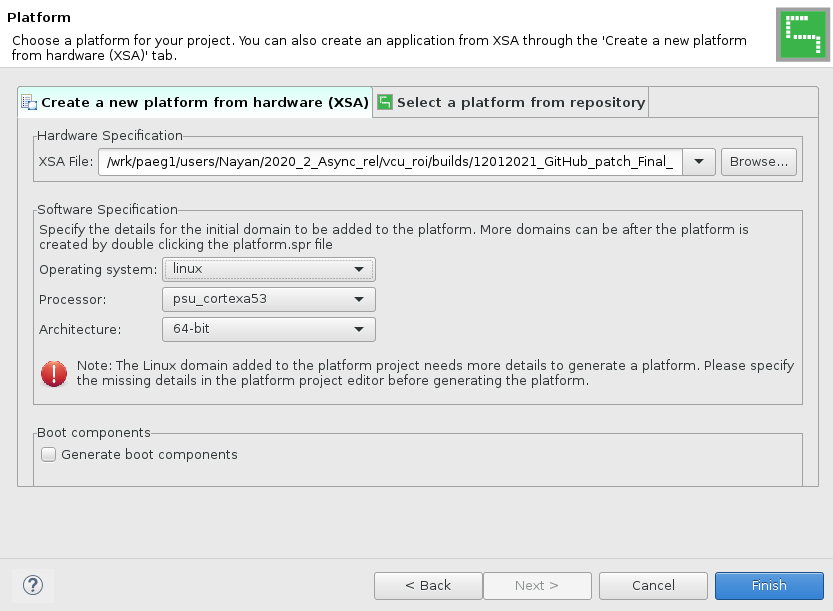
In the Platform Project dialog box, choose Create a new platform from hardware specification (XSA) and provide the XSA path
For prebuild XSA use
TRD_HOME/pl/prebuild/pathFor generated XSA using vivado build use
TRD_HOME/pl/build/zcu106_ROI_HDMI/zcu106_ROI_HDMI.xsa/path
Use below setting under Software Specification
Select
linuxas the operating system,psu_cortexa53as processor, and64-bitarchitecture to create the platformUncheck the box for Generate boot components
Click Finish to create your platform project
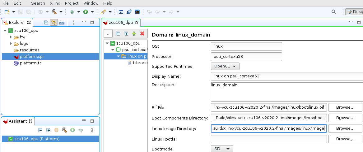
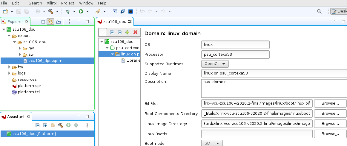
Go to zcu106_dpu > psu_cortexa53 > linux on psu_cortexa53 and add path of required files in Domain: linux_domain
Give the bif file, boot directory, image path, and rootfs path as shown in below figure
Use
<Path to Petalinux Project>/xilinx-vcu-roi-zcu106-v2020.2-final/images/linux/boot/linux.biffor Bif FileUse
<Path to Petalinux Project>/xilinx-vcu-roi-zcu106-v2020.2-final/images/linux/boot/for Boot Components DirectoryUse
<Path to Petalinux Project>/xilinx-vcu-roi-zcu106-v2020.2-final/images/linux/imagefor Linux Image Directory
Right click on the zcu106_dpu project in the Explorer tab and click on Build Project to generate the platform as shown in below figure
The Console tab shows the status of the platform generation.
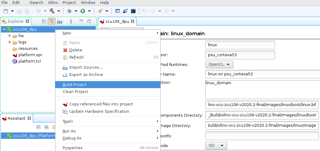
As shown in below image, zcu106_dpu.xpfm is created under zcu106_dpu > export > zcu106_dpu > zcu106_dpu.xpfm
1.7.5 DPU Build
It is recommended to follow the build steps in sequence
Make sure parted utility is installed for DPU build
Clone the Vitis-AI repository and apply patch to add support of ZCU106 in Vitis DPU TRD.
git clone https://github.com/Xilinx/Vitis-AI.git
cd Vitis-AI
git checkout tags/v1.3 -b v1.3
git am $TRD_HOME/dpu/0001-Added-ZCU106-configuration-to-support-DPU-in-ZCU106.patch
The following tutorials assume that the DPU_TRD_HOME environment variable is set as given below.
export DPU_TRD_HOME =<Vitis AI path>/dsa/DPU-TRD
The following tutorials assume that the Vitis and XRT environment variable is set as given below.
Open a Linux terminal. Set the Linux as Bash mode.
source <vitis install path>/Vitis/2020.2/settings64.sh
source <xrt install path>/xilinx/xrt/setup.sh
The default setting of DPU is B4096 with
RAM_USAGE_LOW, CHANNEL_AUGMENTATION_ENABLE, DWCV_ENABLE, POOL_AVG_ENABLE, RELU_LEAKYRELU_RELU6, Softmax. Read theDPU_TRD_HOME/prj/Vitis/dpu_conf.vhfile to get the details of DPU. You can get all the configurations form PG338. Modify theDPU_TRD_HOME/prj/Vitis/dpu_conf.vhfile can change the default settings.Copy dpu_conf.vh file to enable the URAM for ZCU106/ZCU104 DPU Build, The DPU will replace the bram to the uram.
cp TRD_HOME/dpu/dpu_conf.vh DPU_TRD_HOME/prj/Vitis/dpu_conf.vh
Build the hardware design
cd $DPU_TRD_HOME/prj/Vitis
export EDGE_COMMON_SW=<Path to Petalinux Project>/xilinx-vcu-roi-zcu106-v2020.2-final/images/linux/
export SDX_PLATFORM=<Path to Vitis Workspace>/zcu106_dpu/export/zcu106_dpu/zcu106_dpu.xpfm
make KERNEL=DPU DEVICE=zcu106_dpu
Generated SD card files are in
DPU_TRD_HOME/prj/Vitis/binary_container_1/sd_card(SD card Format)Copy generated dpu build images from
DPU_TRD_HOMEdirectory toTRD_HOMEdirectorycd DPU_TRD_HOME/prj/Vitis/binary_container_1/sd_card cp bd.hwh BOOT.BIN boot.scr dpu.xclbin Image system.dtb TRD_HOME/image/boot cp TRD_HOME/apu/vcu_petalinux_bsp/xilinx-vcu-roi-zcu106-v2020.2-final/images/linux/rootfs.ext4 TRD_HOME/image/root
For more detail please refer DPU Build Flow
For more details on Vitis AI, check User Guide (UG1414)
2 Other Information
2.1 Known Issues
For Petalinux related known issues please refer PetaLinux 2020.2 - Product Update Release Notes and Known Issues.
For VCU related known issues please refer AR# 66763: LogiCORE H.264/H.265 Video Codec Unit (VCU) - Release Notes and Known Issues and Xilinx Zynq UltraScale+ MPSoC Video Codec Unit.
2.2 Limitations
For Petalinux related limitations please refer PetaLinux 2020.2 - Product Update Release Notes and Known Issues.
For VCU related limitations please refer AR# 66763: LogiCORE H.264/H.265 Video Codec Unit (VCU) - Release Notes and Known Issues, Xilinx Zynq UltraScale+ MPSoC Video Codec Unit and PG252 link.
2.3 Optimum VCU Encoder parameters for use-cases
Video streaming:
Video streaming use-case requires a very stable bitrate graph for all pictures
It is good to avoid periodic large Intra pictures during the encoding session
Good to avoid periodic Intra frames instead use low-delay-p (IPPPPP…)
VBR is not a preferred mode of streaming
Performance: AVC Encoder settings:
It is preferred to use 8 or higher slices for better AVC encoder performance
AVC standard does not support Tile mode processing which results in the processing of MB rows sequentially for entropy coding
Quality: Low bitrate AVC encoding:
The high profile enables 8x8 transform which results in better video quality at low bitrates
3 Appendix A - Input Configuration File (input.cfg)
The example configuration files are stored at /media/card/config/ folder.
Configuration Type | Configuration Name | Description | Available Options |
|---|---|---|---|
Common | Common Configuration | It is the starting point of common configuration | |
Num of Input | Provide the number of inputs. It will be 1 only due to single-stream support | 1 | |
Output | Select the video interface | HDMI | |
Out Type | Type of output | display, stream | |
Display Rate | Pipeline frame rate | 30 fps | |
Exit | It indicates to the application that the configuration is over | ||
Input | Input Configuration | It is the starting point of the input configuration | |
Input Num | Due to single stream support, there will be 1 input configuration only | 1 | |
Input Type | Input source type | HDMI, Stream | |
Uri | File path or Network URL. Applicable for file playback and stream-in pipeline only. |
| |
Raw | To tell the pipeline is processed. Pass-through is not supported. | False | |
Width | The width of the live source | 3840, 1920 | |
Height | The height of the live source | 2160, 1080 | |
Enable Roi | Enable or Disable ROI in the pipeline. | True, False | |
Relative QP | The difference of QP value than a neighboring pixel for the ROI region to change the quality of the ROI region. | 32 to -31 (poor to best) | |
Exit | It indicates to the application that the configuration is over | ||
Encoder | Encoder Configuration | It is the starting point of encoder configuration | |
Encoder Num | Due to single-stream support, there will be 1 encoder configuration only | 1 | |
Encoder Name | Name of the encoder | AVC, HEVC | |
Profile | Name of the profile | AVC: baseline, main or high | |
Rate Control | Rate control options | CBR, low-latency | |
Filler Data | Filler Data NAL units for CBR rate control | True, False | |
QP | QP control mode used by the VCU encoder | Uniform, Auto, Roi | |
L2 Cache | Enable or Disable L2Cache buffer in encoding process | True, False | |
Latency Mode | Encoder latency mode. | Normal, sub_frame | |
Low Bandwidth | If enabled, decrease the vertical search range used for P-frame motion estimation to reduce the bandwidth. | True, False | |
Gop Mode | Group of Pictures mode. | Basic, low_delay_p | |
Bitrate | Target bitrate in Kbps | 1000-1500 | |
B Frames | Number of B-frames between two consecutive P-frames | 0 | |
Slice | The number of slices produced for each frame. Each slice contains one or more complete macroblock/CTU row(s). Slices are distributed over the frame as regularly as possible. If slice-size is defined as well more slices may be produced to fit the slice-size requirement. | 4-22 4Kp resolution with HEVC codec | |
GoP Length | The distance between two consecutive I frames | 1-1000 | |
Format | The format of input data | NV12 | |
Preset | Based on provided six presets, predefined configuration will be set for encoder parameters. Select custom to provide user-specific options for encoder parameters. | custom | |
Exit | It indicates to the application that the configuration is over | ||
Streaming | Streaming Configuration | It is the starting point of streaming configuration. | |
Streaming Num | Due to single-stream support, there will be 1 streaming configuration only | 1 | |
Host IP | The host to send the packets to the client |
| |
Port | The port to send the packets to port number | 5004 | |
Exit | It indicates to the application that the configuration is over. | ||
Trace | Trace Configuration | It is the starting point of trace configuration | |
FPS Info | To display achieved frame per second information on the console | True, False | |
APM Info | To display APM counter number on the console | True, False | |
Pipeline Info | To display pipeline info on console | True, False | |
Loop Playback | To play display pipeline in the loop | True, False | |
Exit | It indicates to the application that the configuration is over |
4 Appendix B - HDMI-Rx Link-up
HDMI source can be locked to any resolution. To check the link status, resolution and video node of the HDMI input source, run below
media-ctlcommand.media-ctl -p -d /dev/media0
To check the link status, resolution and video node of the HDMI input source, run below
media-ctlcommand.media-ctl -p -d /dev/media0
When HDMI source is connected to 4Kp30 resolution, it shows:
root@zcu106_vcu_trd:/media/card# media-ctl -p -d /dev/media0
Media controller API version 5.4.0

Media device information
------------------------
driver          xilinx-video
model           Xilinx Video Composite Device
serial
bus info
hw revision     0x0
driver version  5.4.0

Device topology
- entity 1: vcap_hdmi_input_v_proc_ss_0 out (1 pad, 1 link)
            type Node subtype V4L flags 0
            device node name /dev/video0    -----> Video node for HDMI-Rx source
        pad0: Sink
                <- "a0040000.v_proc_ss":1 [ENABLED]

- entity 5: a0040000.v_proc_ss (2 pads, 2 links)
            type V4L2 subdev subtype Unknown flags 0
            device node name /dev/v4l-subdev0
        pad0: Sink
                [fmt:RBG888_1X24/3840x2160 field:none]
                <- "a0000000.v_hdmi_rx_ss":0 [ENABLED]
        pad1: Source
                [fmt:VYYUYY8_1X24/3840x2160 field:none]
                -> "vcap_hdmi_input_v_proc_ss_0 out":0 [ENABLED]

- entity 8: a0000000.v_hdmi_rx_ss (1 pad, 1 link)
            type V4L2 subdev subtype Unknown flags 0
            device node name /dev/v4l-subdev1
        pad0: Source
                [fmt:RBG888_1X24/3840x2160 field:none]
                [dv.caps:BT.656/1120 min:0x0@25000000 max:4096x2160@297000000 stds:CEA-861,DMT,CVT,GTF caps:progressive,reduced-blanking,custom]
                [dv.detect:BT.656/1120 3840x2160p30 (4400x2250) stds:CEA-861 flags:CE-video]  -----> Resolution and Frame-rate of HDMI-Rx source
                -> "a0040000.v_proc_ss":0 [ENABLED]
Check resolution and frame-rate of dv.detect under v_hdmi_rx_ss node
When the HDMI source is not connected, it shows:
root@zcu106_vcu_trd:/media/card# media-ctl -p -d /dev/media0
Media controller API version 5.4.0

Media device information
------------------------
driver          xilinx-video
model           Xilinx Video Composite Device
serial
bus info
hw revision     0x0
driver version  5.4.0

Device topology
- entity 1: vcap_hdmi_input_v_proc_ss_0 out (1 pad, 1 link)
            type Node subtype V4L flags 0
            device node name /dev/video0          -----> Video node for HDMI-Rx source
        pad0: Sink
                <- "a0040000.v_proc_ss":1 [ENABLED]

- entity 5: a0040000.v_proc_ss (2 pads, 2 links)
            type V4L2 subdev subtype Unknown flags 0
            device node name /dev/v4l-subdev0
        pad0: Sink
                [fmt:RBG888_1X24/3840x2160 field:none]
                <- "a0000000.v_hdmi_rx_ss":0 [ENABLED]
        pad1: Source
                [fmt:VYYUYY8_1X24/3840x2160 field:none]
                -> "vcap_hdmi_input_v_proc_ss_0 out":0 [ENABLED]

- entity 8: a0000000.v_hdmi_rx_ss (1 pad, 1 link)
            type V4L2 subdev subtype Unknown flags 0
            device node name /dev/v4l-subdev1
        pad0: Source
                [fmt:RBG888_1X24/3840x2160 field:none]
                [dv.caps:BT.656/1120 min:0x0@25000000 max:4096x2160@297000000 stds:CEA-861,DMT,CVT,GTF caps:progressive,reduced-blanking,custom]
                [dv.query:no-link]                ------> HDMI-RX link status
                -> "a0040000.v_proc_ss":0 [ENABLED]
Here dv.query:no-link under v_hdmi_rx_ss node shows HDMI-Rx source is not connected or HDMI-Rx source is not active(Try waking up the device by pressing a key on remote).