Zynq-7000 AP SoC Low Power Techniques part 1 - Installing and Running the Power Demo Tech Tip
Document History
| Date | Version | Author | Description of Revisions |
| 14/04/14 | 0.1 | Yashu Gosain | Initial Revision |
| 03/09/2014 | 0.2 | Yashu Gosain | Enhancements |
Summary
As technology is evolving, electronic devices are becoming compact and performing much more complex operations which significantly increase power consumption. Due to that, device manufacturers put significant efforts to develop different scenarios to save power along with addition of new features to devices.This Tech-tip intention is to show actual power consumption of Zynq-7000 AP SoC FPGA while performing different scenarios in Processing section (PS) as well as Programmable logic (PL). It also displays chip junction temperature during different scenarios execution. By executing these scenarios on both PS and PL, user can use the actual power consumption information to predict the Power budget of their real application.
It also demonstrates power consumption during execution of Ubuntu desktop application on Zynq. User can execute applications and perform different I/O operation on Zynq PS peripheral supported by Ubuntu desktop to measure power consumption. It helps user to predict their system power consumption.
Implementation
| Implementation Details | |
| Design Type | PS + PL |
| SW Type | Linux |
| CPUs | 2 ARM Cortex-A9 |
| PS Features |
|
| Boards/Tools | ZC702 |
| Xilinx Tools Version | Vivado 2103.4 |
| Xilinx Linux Kernel Version | xilinx-v2013.4 |
| Board | ZC702 Rev 1.0 |
| Files Provided | |
| Zynq7000AP_SOC_PowerDemo_V2.0.zip | See Appendix A for the descriptions of the files |
Description
The ZC702 board uses power regulators and a PMBus compliant system controller from Texas Instruments (TI) to supply core and auxiliary voltages. The ZC702 board uses 12 V Input supply to power the board. There are switching regulators (PTD08D210W) and 1 linear regulator which generate different voltages required for the Zynq as well as the on-board components present on the ZC702 board. The voltage output of these regulators are monitored and controlled by three TI power controllers (UCD9248PFC).
For Power measurement, this Tech-Tip reads the power values measured by the TI digital power controllers (UCD9248) on ZC702 and converts them to real world values and send to host application via UART terminal.
Refer to Zynq-7000 AP SoC Measuring ZC702 Power using Linux Application Tech Tip to get details about Linux application used for power measurements and corresponding interface between Zynq and TI Digital power controllers.
This document provides details about measuring Zynq power consumption by executing different configuration. Different configurations are as follow:
- PS Configuration: Design provided with this Tech-tip supports following PS configuration
- CPU Loading: CPU loading means executing single or dual threads on single/both CPUs. In this configuration, user can select to load one CPU or both of them. It is done by executing one of the Spec CPU2000 benchmark named 186.crafty on CPUs. Refer to 186.crafty Spec CPU-2000 benchmark for more details.
- CPU Frequency scaling: CPU frequency scaling enables the operating system to scale the CPU frequency up or down in order to save power. CPU frequency scaling is implemented in Linux kernel, the infrastructure is called cpufreq. Refer to cpu-freq framework for more details. CPU Frequencies supported in cpufreq framework for ZYNQ are as follow:
- 667 MHz
- 333 MHz
- 222 MHz
- 33 MHz
- User can switch between any of frequencies during execution and do measurements.
- CPU Idle: In this configuration, both CPUs utilization forcefully becomes zeros (idle).
- PL Configuration: Design used to configure PL logic is referenced from XAP555 application note for Virtex-7 FPGAs. XAPP555 reference design is modified for ZYNQ and ported on ZC702 board. It contains 254 numbers (maximum) of Power Consuming And Speed Test Modules (PCASTM) connected in serial chain.
PL Configurations provides following configurations:
- PL Resource Utilization: In this configuration, user can selectively choose numbers of PCASTM module in serial chains to vary PL resource utilization.
- PL Frequency Scaling: In this scenario, user can select PL logic operating clock frequency between 0 MHz to 200 MHz (steps of 50 MHz).
- Ubuntu Desktop: This configuration is separate from above two configurations. If user selects this configuration, system reboots automatically and executes Ubuntu desktop application on ZYNQ. This configuration also supports CPU frequency scaling framework as stated above. User can execute applications and does any IO transfer on ZYNQ peripherals as supported by Ubuntu desktop to monitor power consumption, chip junction temperature etc.
Design Overview
Zynq Power Demo is broadly divided in two components:- Host machine Application: It is C# based Graphical User Interface (GUI) program executing on the host machine (Windows machine). Its responsibilities are as follows:
- Provides different configuration options to user to select.
- It encapsulate selected configuration in command and send it to target board i.e. ZC702 board.
- Wait to receive command response from it.
- Plot graphs related Power consumption of different ZYNQ power rails and CPUs utilization depending on the information received from the target board.
- Displays Chip Junction temperature.
- It also displays text response of each command on display window.
- Provides option to switch between Ubuntu Desktop and PS+ PL application.
- Target Board Application: It is Linux Application running on ZC702 board. Main job are as follows
- To receive commands from the Host machine software and do necessary configurations related to Zynq device accordingly.
- Sends response of the received command to Host machine application.
- Continuously send the power consumption information of all ZYNQ power rails and CPUs statistics to Host machine software in every 0.5 msec.
- It reads chip junction temperature using XADC interface and sends it to host machine application.
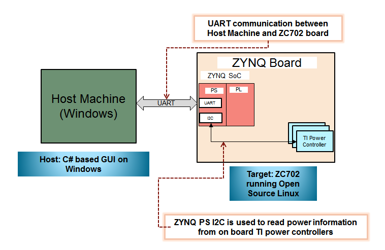
| Figure 1: Block Diagram |
As stated in block diagram, UART is mode of communication between ZC702 board and Host machine application. ZYNQ PS UART acts as master device which is connected to Host machine which act as slave device.
In ZC702 board, PS I2C block is used to read power measurement done by TI digital power controller.
Host Machine Application Description
Host machine application is C# based GUI program executing on windows machine. It sends commands and receives different kind responses from ZC702 board. Below figures shows Host machine GUI application:| Figure 2: GUI |
It is broadly divided in following sections:
- COM port Selection: Once ZC702 board is connected with host machine via USB to Mini USB for USB-UART, GUI automatically detects and shows the connected COM port in drop down list. User needs to select appropriate COM port to connect with the target board.
- System Settings: Options provided in system setting are static option which means by changing any of them will reboots the system.Following are the available options
- Ubuntu: By checking this option boots system to execute Ubuntu desktop application. Un-checking this options boots the system with Linux.
- DDR frequency: User can change DDR frequency by selecting available frequency in drop down menu. It provides following two options:
- 533 MHz
- 400 MHz
- Configuration section: Option provided in Configuration sections can be change run time. It available options depend on the Ubuntu check box selection. Following are option available:
- Ubuntu option unchecked: In this case following are the available options:
- PS configuration options:
- PS Frequency: This selection box provides CPU frequency scaling at run time. Available frequencies are 667 MHz, 333 MHz, 222 MHz and 33MHz. User can switch to any option during execution.
Note: If user selected 33 MHz, than system response time become very slow. Even after selecting 33 MHz every other option configuration wizard become disable. - PS Load: This selection box provides following options:
- CPU_IDLE: In this mode, both CPU goes to idle state. It means both CPU utilization goes to 0%.
- SPEC 2000: 1 Load: It triggers Spec CPU2000 benchmark named 186.carfty single thread execution on single CPU. In this case one of the CPU utilization goes to 100%
- SPEC 2000: 2 Load: It triggers execution of two separate threads (186.carfty) on both CPUs. In this case both CPU utilization goes to 100%
- STANDBY: It is low power state for Zynq, in which all peripherals goes to low power mode and DDR goes in to self-refresh mode. CPU waits for interrupt for resume. As Linux application layer is freeze in this mode, than user needs to do power measurement using TI USB Fusion cable. Refer to ZC702 Power using TI Fusion Power Designer Tech Tip to know about measuring power.
Note: To measure PS Logic power during suspend, measure VCCPINTand VCCPAUX power rail using TI fusion cable and add both of them. Power Rails measured using TI fusion cable includes the board static power also. In the final calculation, user need to subtract the static component from the actual measurement to get actual PS logic power consumption. Other thing user need to considered during suspend mode, some of the PS MIOs are not disabled. Like Ethernet uses HSTL class I I/O which adds up VCCPAUX power consumption.
- PL Configuration options:
- PL Frequency: In this option, user can select PL operating frequency of Logic from 0 MHz to 200 MHz. Available options are 0, 50, 100, 150, 200 MHz.
- PL Utilization: By this option, user can select number of PCASTM in a serial chain. Available options are 0, 25, 50, 75, 100%. 100% stand for 254 PCASTM in serial chain. 50% indicates 127 PCASTM in serial chain and rest of PCASTM is disabled.
- Accumulator: It is to enable accumulator option in PCASTM chain.
- LFSR: It is to enable LFSR option in PCASTM chain.
- Toggle F/F: It is to enable T F/F option in PCASTM chain. Refer to http://www.wiki.xilinx.com/Zynq-7000+AP+SoC+PS+Control+of+PL+for+Power+Management tech tip for more details about PCASTM modules.
- Demo Check Box: If this option is checked than it start executing different combination of PS configuration options automatically for 35 sec apart.
- PS Frequency: This selection box provides CPU frequency scaling at run time. Available frequencies are 667 MHz, 333 MHz, 222 MHz and 33MHz. User can switch to any option during execution.
- PS configuration options:
- Ubuntu Check box checked: In this case, following options are available:
- PS Frequency: This selection box provides CPU frequency scaling at run time. Available frequencies are 667 MHz, 333 MHz and 222 MHz. User can switch to any option during execution. Users can execute application and do different IO operations on PS peripherals supported by Ubuntu desktop and monitor power numbers.
- Ubuntu option unchecked: In this case following are the available options:
- Power Selection: It provides a drop down menu with following option:
- Calculated PWR: If this option is selected than power consumption numbers read from power regulators are subtracted with board static power and get displayed in Demo status section.
- Regulator PWR: If this option is selected than Demo status section displays power consumption numbers read from power regulators.
- Demo Status section: In all above configurations,status section displays following graphs and information
- Chip Junction Temperature.
- CPUs utilization graphs wrt. time
- It provides selection box to select any of Zynq power rail to monitor. Depending on user selections plots following graphs for selected Zynq Power Rails
- Power wrt. time.
- Current wrt. time.
- Current CPU and DDR operation frequency
- Total PL power graph wrt. time
- Total PS+ DDR power graph wrt. time
- PS logic power graph wrt. time
- PS mem + DDR power graph wrt. Time
- It provides selection between Total Calculated power and regulated power.
- Total regulated power = PS Logic + PS I/O + PS mem + DDR + PL power
- Total calculated Power = Total regulated power - PS static power
Depending on Power Selection selected option, it plots following graphs
- Total Calculated power wrt. time
- Total Regulator power wrt. time
- Serial Console section : It is used to display the response from ZC702 board via UART. It also helps in debugging the execution on the ZC702 board.
Power Demo Setup:
This section discusses Power demo setup details. Design file link is provided along with this Tech-Tip. This file should be extracted to a directory calleddesign. Design directory includes following directories:- GUI: It includes following files
- ZedGraph.dll: It is dynamic link libraries for GUI application.
- ZynqPowerDemo.exe: It is Host machine application. It needs to execute to start GUI application.
- Executable: It includes “Zynq_powerDemo.img” executable file which needs to be programmed to SD card. Details about programming this file to SD card is provided in the subsequent sections
ZC702 board Setup:
- ZC702 board and related power supply
- 8GB and above SD Card to hold executables
- USB to Mini USB for USB-UART
- PC
- Host machine Application.
Connect the cables as shown in Figure below to prepare the ZC702 board to run the Power Demo applications
- Connect an USB Mini-B cable into the Mini USB port J17 labeled USB UART on the ZC702 board and the USB Type-A cable end into an open USB port on the host PC for UART communications.
- Connect the power supply to the ZC702 board. Do not switch the power on.
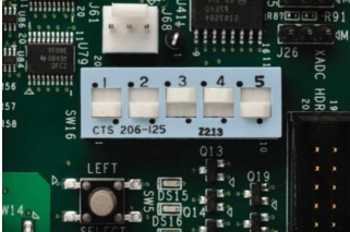
- Make sure the switches are set as shown in figure below, which allows the ZC702 board to boot from the SD-MMC card
Figure 4: Switch setting for SD card boot mode SD card setup:
http://sourceforge.net/projects/win32diskimager/
Follow following procedure to copy power demo executables to SD card
- Place the SD card in card reader and connect to the Windows PC.
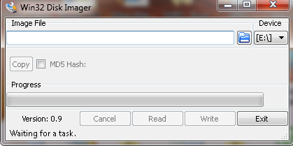
- Execute “Win32Diskimager.exe”. It opens Win32 Disk Imager wizard
Figure 5: Win32 Disk Imager Wizard - Under ‘Image file’ option, select the location of (.img) file. It provided under design/Executable folder.
- Under ‘Device’ option, select SD card drive. Then Click Write option.This step allows the Win32Discimager to create following two partitions
- FAT Partition
- EXT3 Partition Than it write FAT partition files to SD card FAT partition and EXT3 partition files to SD EXT3 partition
- Wait for write operation to complete
Application Execution:
Follow the following procedure for Power Demo execution- Make sure that the hardware board is set up is done properly as discussed in above section ZC702 board setup.
- Insert a SD-MMC memory card, which contains power demo executables, into the SD slot on the ZC702 board
- Copy design/GUI folder in Windows host machine which is connected to target board.
- Open Power Demo GUI Application on host machine, by double clicking ZynqPowerDemo.exe under GUI folder.
- Switch ON Zc702 board.
- In Power Demo GUI application, select appropriate COM port in top left hand side under “select Com port”.
- Check print messages in the Serial console (bottom side) of GUI application.
- After Linux boots up, “APPLY” button on GUI application becomes activated.
- Do any configuration in “Configuration” section (at top) and press “APPLY” to initiate command from GUI application to ZC702 board.
- Once command is received by ZC702 board, it do appropriate setting depending on the user selected configuration and start sending power measurement along with other information.
- In “Demo status” section following user options are available
- User can select any of one of Zynq Power rail in “RAIL” selection box to monitor respective power as well as current consumption.
- User can also select to monitor between calculated/ regulated power. This selection box is provided in “Demo status” middle left hand side.
Switching between different Application:
Host machine GUI application provide a check box option to switch between Ubuntu desktop application and PS/PL application. This check option is available in “System Settings” Section as highlighted below:| Figure 6: System Settings |
If this check box option is selected, than it automatically initiate rebooting of system and executes Ubuntu desktop application on ZC702 board. In this scenario, GUI application supports only PS frequency scaling option that too CPU is in idle state. User can monitor all options in “Demo status”. Follow the following procedure for Power Demo execution
- Check Ubuntu check box options in ”Configuration”.
- Wait for system to reboot and executes Ubuntu Desktop application. Once system booting is complete, “APPLY” button activate automatically.
- To start monitoring in GUI application, user needs to select appropriate PS frequency and set PS load to CPU_IDLE.
- Press “APPLY” button. At this time, GUI receiving measurements from ZC702 board and start populates information in Demo status section
- In the Ubuntu desktop Application, by default screen saver power saving feature during idle condition is enabled . So after every 10 mins. of idle period, screen gets lock automatically. To unlock it, provide password as "root"
- To disable the screen saver power saving feature, open terminal in Ubuntu desktop and execute following command
gsettings set org.gnome.desktop.lockdown disable-lock-screen 'true'
It disables Ubuntu screen saver power saving feature. - User can execute any Ubuntu desktop supported application and I/O transfer using PS peripherals and monitor power consumption, CPU utilization, chip temperature etc. in ” Demo status” section of GUI application.
Settings DDR frequency :
Host machine GUI application provide drop down menu option to select between available DDR frequency . This drop down option is available under DDR freq in “System Settings” Section as highlighted below:| Figure 7: System Settings |
If this option is changed, than it automatically initiate rebooting of system.Note: Changing DDR frequency option is only available when Ubuntu check box option is not selected in System settings.
Appendix A: File Descriptions in design directory:
Directory Structure is- design
- GUI:
- ZedGraph.dll: It is dynamic link libraries for GUI application.
- ZynqPowerDemo.exe: It is Host machine application. It needs to execute to start GUI application
- Executable:
- Zynq_powerDemo.img: Zynq Power Demo executable file.
- GUI:


