Zynq Ultrascale MPSoC Multiboot and Fallback
1.0 Zynq UltraScale+ MPSoCMultiboot and Fallback
This page will describe procedures to make images for Multiboot and fallback use case scenarios of booting on ZCU102 board.
1.1 ZCU102 Mutltiboot and Fallback Procedures
1. Multiboot Procedure for A53 first then R5 in Non Secure SD boot mode
2. Multiboot Procedure for R5 first then A53 in Non Secure SD boot mode
3. Mutliboot Procedure for Standalone Application in Secure SD boot mode
4. Fallback Procedure for A53 first then R5 in Non Secure SD boot mode
5. Fallback Procedure for R5 first then A53 in Non Secure SD boot mode
6. Fallback Procedure for Standalone Application in Secure SD boot mode
Note:
1. Multiboot and fallback boot images(boot.bin, boot000x.bin) should be made with using same key
in encryption for Secure boot mode.
2. Multiboot and fallback boot images(boot.bin, boot000x.bin) should be made with using same key
in authentication for Secure boot mode.
3. Multiboot and fallback boot images(boot.bin, boot000x.bin) should be in Non-Secure mode.
1.1.1 Multiboot using A53's boot first and then R5 in Non-Secure SD boot mode
1. Refer to Generate images section of PetaLinux in Non Secure mode
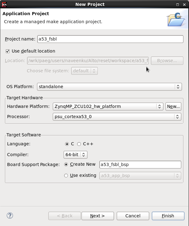
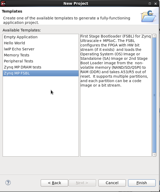
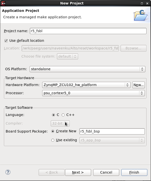
2. Build the FSBL for A53 using SDK as follows
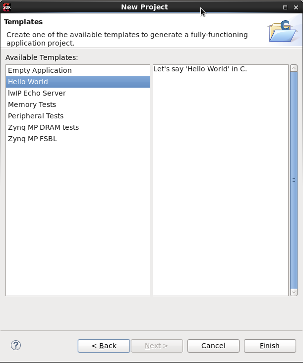
3. Build the R5 hello world app using SDK as follows


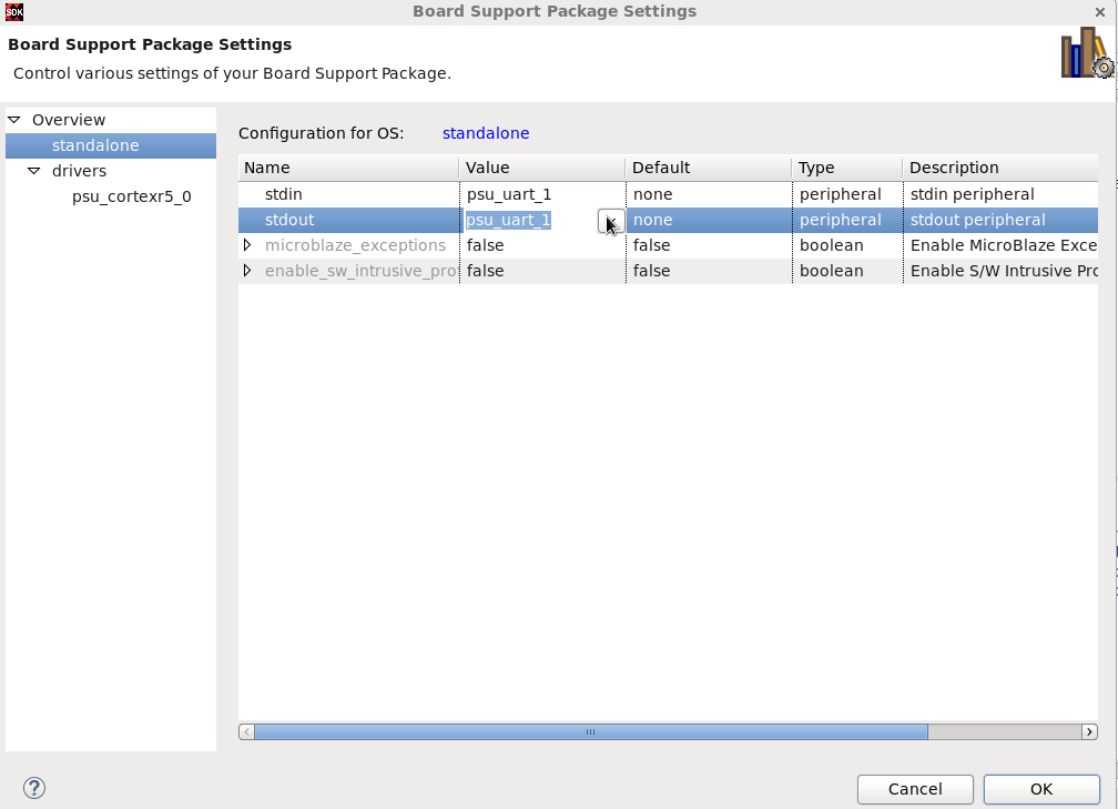
4.To select the UART1 for R5-0, configuration settings using SDK as follows.
5. Multiboot mode register should be updated with count required for the user. Modified FSBL code as follows
- In
, after fsbl init success add the XFsbl_UpdateMultiBoot() with the user required count.For example count as 2View file name xfsbl_main.c - Build the FSBL
Note: xfsbl_main.c file can be changed and used as reference file.
6. Create the boota53_mb.bif file as follows to boot from SD card with modified FSBL code
| Code Block | ||
|---|---|---|
| ||
the_ROM_image:
{
     [fsbl_config] a53_x64
     [pmufw_image] xpfw.elf
     [bootloader] zynq_mb_fsbl.elf
     [destination_cpu=a53-0] bl31.elf
     [destination_cpu=a53-0] u-boot.elf
     [destination_cpu=r5-0] r5_app.elf
} |
7. Create the boot.bin as follows
| Code Block | ||
|---|---|---|
| ||
bootgen -image boota53_mb.bif -arch zynqmp -w -o i boot.bin |
8. Create the boota53.bif file as follows to boot from SD card with the images built using PetaLinux
| Code Block | ||
|---|---|---|
| ||
the_ROM_image:
{
     [fsbl_config] a53_x64
     [pmufw_image] xpfw.elf
     [bootloader] zynq_fsbl.elf
     [destination_cpu=a53-0] bl31.elf
     [destination_cpu=a53-0] u-boot.elf
     [destination_cpu=r5-0] r5_app.elf
} |
9. In SD card multiboot mode, boot.bin image naming convention should be boot000x.bin. So create the boot0001.bin and boot0002.bin as follows
| Code Block | ||
|---|---|---|
| ||
bootgen -image boota53.bif -arch zynqmp -w -o i boot0001.bin cp boot0001.bin boot0002.bin |
10. Copy the boot.bin, boot0001.bin, boot0002.bin and image.ub to SD card
11. Insert the SD card and power on the board.Switch setting as follows
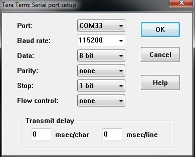
12. Connect the console with the following settings for both COM interface 0 as UART0 and COM interface 1 for UART1
13. Board should boot with BOOT0002.bin as follows in FSBL fetch from A53 then R5 on UART0 and Hello world message in UART1.
The following log is displayed on the screen
| Code Block | ||
|---|---|---|
| ||
Processor Initialization Done ================= In Stage 2 ============ SD1 Boot Mode SD: rc= 0 File name is BOOT0002.BIN Multiboot Reg : 0x2 Image Header Table Offset 0x8C0 *****Image Header Table Details******** |
| Code Block | ||
|---|---|---|
| ||
Hello World in R5-0 |
1.1.2 Multiboot Procedure for R5 first then A53 in Non-Secure SD boot mode
1. Refer to generate images section of PetaLinux in Non Secure mode
2. Build the FSBL for R5 using SDK as follows
- In
, after fsbl init success add the XFsbl_UpdateMultiBoot() with the user required count.For example count as 2View file name xfsbl_main.c - Build the FSBL
4. Create the bootr5_mb.bif file as follows to boot from SD card with modifed fsbl code
| Code Block | ||
|---|---|---|
| ||
the_ROM_image:
{
    [fsbl_config] r5_single
    [pmufw_image] xpfw.elf
    [bootloader] zynqmp_fsbl_mb_r5.elf
    [destination_cpu=a53-0] bl31.elf
    [destination_cpu=a53-0] u-boot.elf
} |
| Code Block | ||
|---|---|---|
| ||
bootgen -image bootr5_mb.bif -arch zynqmp -w -o i boot.bin |
6. Create the bootr5.bif file as follows to boot from SD card with modified FSBL code
| Code Block | ||
|---|---|---|
| ||
the_ROM_image:
{
     [fsbl_config] r5_single
     [pmufw_image] xpfw.elf
     [bootloader] zynqmp_fsbl_r5.elf
     [destination_cpu=a53-0] bl31.elf
     [destination_cpu=a53-0] u-boot.elf
} |
| Code Block | ||
|---|---|---|
| ||
bootgen -image bootr5.bif -arch zynqmp -w -o i boot0001.bin cp boot0001.bin boot0002.bin |
8. Copy the boot.bin, boot0001.bin, boot0002.bin and image.ub to SD card
9. Insert the SD card and power on the board.Switch settings as follows
11. Connect the console with the following settings
12. Board should boot with BOOT0002.bin as follows in FSBL from R5 then u-boot should boot from A53
| Code Block | ||
|---|---|---|
| ||
Processor Initialization Done ================= In Stage 2 ============ SD1 Boot Mode SD: rc= 0 File name is BOOT0002.BIN Multiboot Reg : 0x2 Image Header Table Offset 0x8C0 |
1.1.3 Multiboot Procedure using Standalone application in Secure SD boot mode
1. Build the FSBL for A53 using SDK figures as follows
2. Multiboot mode register should be updated with count required for the user. Modified FSBL code as follows
- In
, after fsbl init success add the XFsbl_UpdateMultiBoot() with the user required count.For example count as 2View file name xfsbl_main.c - Build the FSBL
3. Build the A53 hello world app using SDK figures as follows

4. Refer to bbram section for key programming in BBRAM
5. Create the boota53_mb.bif file as follows to boot from SD card with modified FSBL
| Code Block | ||
|---|---|---|
| ||
the_ROM_image:
{
     [aeskeyfile] vncbbram1709.nky
     [fsbl_config] a53_x64, bh_auth_enable
     [keysrc_encryption] bbram_red_key
     [auth_params] ppk_select=0; spk_id=0x00000000
     [pskfile] hello_0_SHA3_PSK.pem
     [sskfile] hello_0_SHA3_SSK.pem
     [bootloader, authentication=rsa, encryption=aes] zynqmp_fsbl_mb.elf
     [destination_device=ps, destination_cpu=a53-0, authentication=rsa, encryption=aes] a53-app.elf
} |
6. Create the boot.bin as follows
| Code Block | ||
|---|---|---|
| ||
bootgen -image boota53_mb.bif -arch zynqmp -w -o i boot.bin |
7. Create the boota53.bif file as follows to boot from SD card with modifed fsbl code
| Code Block | ||
|---|---|---|
| ||
the_ROM_image:
{
     [aeskeyfile] vncbbram1709.nky
     [fsbl_config] a53_x64, bh_auth_enable
     [keysrc_encryption] bbram_red_key
     [auth_params] ppk_select=0; spk_id=0x00000000
     [pskfile] hello_0_SHA3_PSK.pem
     [sskfile] hello_0_SHA3_SSK.pem
     [bootloader, authentication=rsa, encryption=aes] zynqmp_fsbl.elf
     [destination_device=ps, destination_cpu=a53-0, authentication=rsa, encryption=aes] a53-app.elf
} |
8. In SD card multiboot, boot.bin image naming convention should be boot000x.bin. So create the boot0001.bin and boot0002.bin as follows
| Code Block | ||
|---|---|---|
| ||
bootgen -image boota53.bif -arch zynqmp -w -o i boot0001.bin cp boot0001.bin boot0002.bin |
9. Copy the boot.bin, boot0001.bin and boot0002.bin to SD card
10. Insert the SD card and power on the board.Switch settings as follows
11. Connect the console with the following settings.
12. Board should boot with BOOT0002.bin as follows in FSBL from A53
| Code Block | ||
|---|---|---|
| ||
Processor Initialization Done ================= In Stage 2 ============ SD1 Boot Mode SD: rc= 0 File name is BOOT0002.BIN Multiboot Reg : 0x2 Image Header Table Offset 0x8C0 |
1.1.4 Fallback procedure for A53's boot first and then R5 in Non-Secure SD boot mode
1. Refer to Generate images section of PetaLinux in Non Secure mode
2. Build the R5 hello world app using SDK as follows
3.To select the UART1 for R5-0, configuration settings using SDK as follows.
4. Create a image boota53_bad.bif file as follows to boot from SD card with zynq_fsbl.elf or change the header to create a bad image
| Code Block | ||
|---|---|---|
| ||
the_ROM_image:
{
       [fsbl_config] a53_x64
       [bootloader] zynq_fsbl.elf
} |
| Code Block | ||
|---|---|---|
| ||
bootgen -image boota53_bad.bif -arch zynqmp -w -o i boot.bin |
| Code Block | ||
|---|---|---|
| ||
the_ROM_image:
{
     [fsbl_config] a53_x64
     [pmufw_image] xpfw.elf
     [bootloader] zynq_fsbl.elf
     [destination_cpu=a53-0] bl31.elf
     [destination_cpu=a53-0] u-boot.elf
     [destination_cpu=r5-0] r5_app.elf
} |
7. Create the boot0001.bin as follows
| Code Block | ||
|---|---|---|
| ||
bootgen -image boota53.bif -arch zynqmp -w -o i boot0001.bin |
8. Copy the boot.bin, boot0001.bin and image.ub to SD card
9. Insert the SD card and power on the board. Switch settings as follows
10. Connect the console with the following settings for both COM interface 0 as UART0 and COM interface 1 for UART1
11. Board should boot with BOOT0001.bin as follows in FSBL from A53 then R5. The following log is displayed on the screen .
| Code Block | ||
|---|---|---|
| ||
Processor Initialization Done ================= In Stage 2 ============ SD1 Boot Mode SD: rc= 0 File name is BOOT0001.BIN Multiboot Reg : 0x1 Image Header Table Offset 0x8C0 *****Image Header Table Details******** |
| Code Block | ||
|---|---|---|
| ||
Hello World in R5-0 |
1.1.5 Fallback Procedure for R5 first then A53 in Non-Secure SD boot mode
1. Refer to generate images section of PetaLinux in Non Secure mode
2. Build the FSBL for R5 using SDK as follows
| Code Block | ||
|---|---|---|
| ||
the_ROM_image:
{
[fsbl_config] r5_single
[bootloader] zynqmp_fsbl_r5.elf
} |
| Code Block | ||
|---|---|---|
| ||
bootgen -image bootr5_bad.bif -arch zynqmp -w -o i boot.bin |
| Code Block | ||
|---|---|---|
| ||
the_ROM_image:
{
    [fsbl_config] r5_single
    [pmufw_image] xpfw.elf
    [bootloader] zynqmp_fsbl_r5.elf
    [destination_cpu=a53-0] bl31.elf
    [destination_cpu=a53-0] u-boot.elf
} |
6. Create the boot0001.bin as follows
| Code Block | ||
|---|---|---|
| ||
bootgen -image bootr5.bif -arch zynqmp -w -o i boot0001.bin |
8. Insert the SD card and power on the board.Switch settings as follows
9. Connect the console with the following settings
10. Board should boot with BOOT0001.bin as follows in FSBL from R5 then A53
| Code Block | ||
|---|---|---|
| ||
Processor Initialization Done ================= In Stage 2 ============ SD1 Boot Mode SD: rc= 0 File name is BOOT0001.BIN Multiboot Reg : 0x1 Image Header Table Offset 0x8C0 |
1.1.6 Fallback Procedure using Standalone application in Secure SD boot mode
1. Build the FSBL for A53 using SDK figures as follows
2. Build the A53 hello world app using SDK figures as follows
4. Create the boota53_bad.bif file as follows to boot from SD card with modified FSBL or change the header to create a bad image
| Code Block | ||
|---|---|---|
| ||
the_ROM_image:
{
     [aeskeyfile] vncbbram1709.nky
     [fsbl_config] a53_x64, bh_auth_enable
     [keysrc_encryption] bbram_red_key
     [auth_params] ppk_select=0; spk_id=0x00000000
     [pskfile] hello_0_SHA3_PSK.pem
     [sskfile] hello_0_SHA3_SSK.pem
     [bootloader, authentication=rsa, encryption=aes] zynqmp_fsbl.elf
} |
5. Create a bad boot.bin image as follows
| Code Block | ||
|---|---|---|
| ||
bootgen -image boota53_bad.bif -arch zynqmp -w -o i boot.bin |
| Code Block | ||
|---|---|---|
| ||
the_ROM_image:
{
     [aeskeyfile] vncbbram1709.nky
     [fsbl_config] a53_x64, bh_auth_enable
     [keysrc_encryption] bbram_red_key
     [auth_params] ppk_select=0; spk_id=0x00000000
     [pskfile] hello_0_SHA3_PSK.pem
     [sskfile] hello_0_SHA3_SSK.pem
     [bootloader, authentication=rsa, encryption=aes] zynqmp_fsbl.elf
     [destination_device=ps, destination_cpu=a53-0, authentication=rsa, encryption=aes] a53-app.elf
} |
| Code Block | ||
|---|---|---|
| ||
bootgen -image boota53.bif -arch zynqmp -w -o i boot0001.bin |
9. Insert the SD card and power on the board.Switch setting as follows
11. Board should boot with BOOT0001.bin as follows
| Code Block | ||
|---|---|---|
| ||
Processor Initialization Done ================= In Stage 2 ============ SD1 Boot Mode SD: rc= 0 File name is BOOT0001.BIN Multiboot Reg : 0x1 Image Header Table Offset 0x8C0 |