...
The Zynq® UltraScale+™ RFSoC ZCU216 kit and RF DC Evaluation Tool includes everything needed for quick out of box evaluation of the excellent Gen 3 DAC/ADC performance. The RF DC Evaluation Tool provides the perfect SW platform for easy generation and acquisition of RF signals to quickly get you moving toward the prototype/development stage. For more information on the ZCU216 boards and its associated add-on cards (XM650, XM655, CLK104), please see XM650, XM655, and CLK104 Add-On Cards Hardware Description
RF Data Converter Evaluation Tool Software Download
...
Assemble the ZCU216 (main board) with the CLK-104 clocking board as shown.

Carefully attach the add-on card extender board with the screws provided.
XM650

XM655
Example: Loopback between DAC Tile 0: DAC 0 and ADC tile 0: ADC 0.
Connect the HC2-to-SMA cables to locations JHC1 and JHC5 and tighten with the hex key provided.
Connect pins 0 and 1 of JHC1 and JHC5 to the 10MHz-to-1GHz baluns on the XM655/616B as show below. We will generate a single tone at 200MHz hence the choice of baluns 10MHz-1GHz. An additional Low Pass Filter (2500MHz) can be added to suppress the DAC image. For other waveforms, a different choice of baluns and additional filters provided can be used.
Use the cable provided to interconnect J13 and J17 and complete the loop-back as shown:

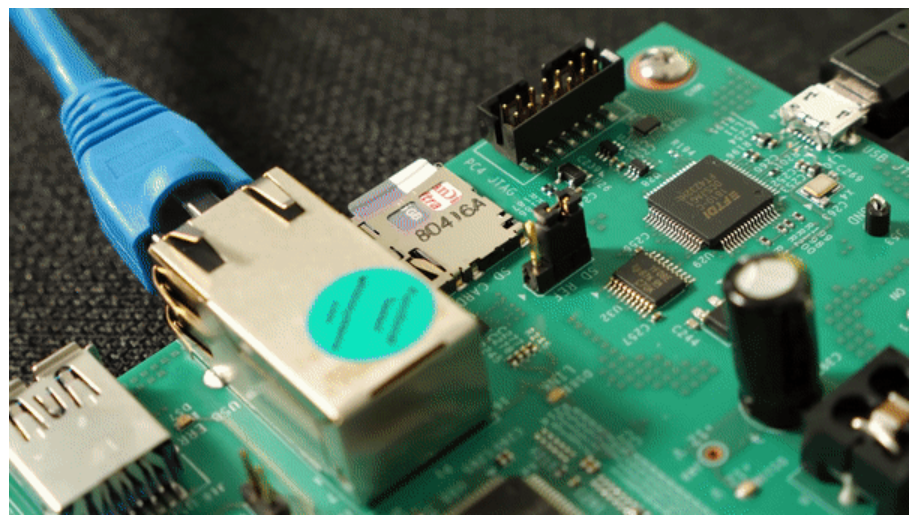
Connect the power and network cables.
The RF DC Evaluation tool uses Windows OS Automatic Private IP Addressing (APIPA) feature so that you only have to connect a network cable between the board and host computer.
For use case where APIPA is not suitable, please see RF DC Evaluation Tool - Network connection and SD card details
Change DIP switch SW2 to SD boot mode. The ZCU216 will have all Jumpers and Switch Settings in their default position when unboxed. If necessary, you can refer to “Default Jumper and Switch Settings” in the ZCU216 Board User Guide to check.

Note the location of power switch.
Note the location of DIP switch SW2.
...
Connect to a power source and turn on the board power using switch SW15.
The board powers on and boots from the SD card using the programmed images.
The DONE and INIT_B LEDs will turn green
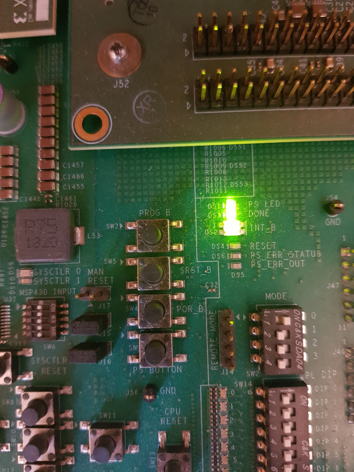

It takes approximately 60s for the operating system to fully boot and for the embedded software to start.
...