Table of Contents
| Table of Contents |
|---|
1 Overview
The primary goal of this VCU ROI design is to demonstrate the use of DPU (Deep learning Processor Unit) block for extracting the ROI (Region of Interest) from input video frames and to use this information to perform ROI based encoding using VCU (Video Codec Unit) encoder hard block present in Zynq UltraScale+ EV devices.
The design will serve as a platform to accelerate Deep Neural Network inference algorithms using DPU and demonstrate the ROI feature of VCU encoder. The design uses a Deep Convolutional Neural Network (CNN) named Densebox, running on DPU to extract ROI Information (e.g. ‘face’ in this case).
The Design will use Vivado IPI flow for building the hardware design and Xilinx Yocto Petalinux flow for software design & DNNDK Toolchain for compiling the Densebox algorithm from Caffe, a high-level ML framework. It will use Xilinx IP and Software driver to demonstrate the capabilities of different components.
The following figure shows one of the use cases (streaming pipeline) with face detection with enhanced encoding for ROI on ZCU106.
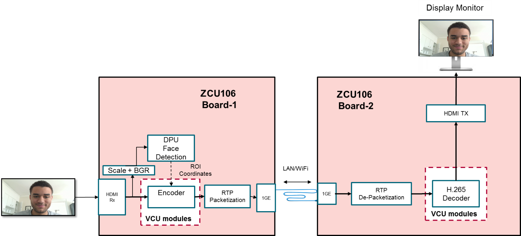
Enhanced encoding for ROI using ZCU106 Boards
1.1 System Architecture
The following figure shows the system level diagram which includes the components of the evaluation board.

1.2 Hardware Architecture
This section gives a detailed description of the blocks used in the hardware design. The functional block diagram of the design is shown in the below figure.
There are seven primary Sections in the design.
HDMI Capture Pipeline:
Captures video frame buffers from Capture source in 4k Resolution, NV12 Format.
writes the buffers into DDR Memory with Frame Buffer Write IP.
Multi-scaler Block:
Reads the Video Buffers from DDR Memory.
Scales down the buffer to the VGA(640x480) size (suitable for dpu).
Converts the format from NV12 to BGR.
Writes the Down-scaled buffer to DDR Memory.
DPU Block:
Reads the downscaled buffers from DDR Memory.
Runs the Densebox algorithm to generate the ROI information for each frame buffer.
Passes the ROI information to VCU Encoder.
VCU Encoder:
Reads the 4k NV12 Buffer from DDR Memory.
Receives the ROI metadata from DPU IP.
Encodes the video buffers based on the ROI Information.
Finally writes the encoded stream to DDR Memory.
PS GEM:
Reads the Encoder stream from DDR Memory.
Streams out the encoded stream via Ethernet.
VCU Decoder:
Decodes the received encoded frame and writes to memory
HDMI Tx:
Displays the decoded frames on HDMI Display
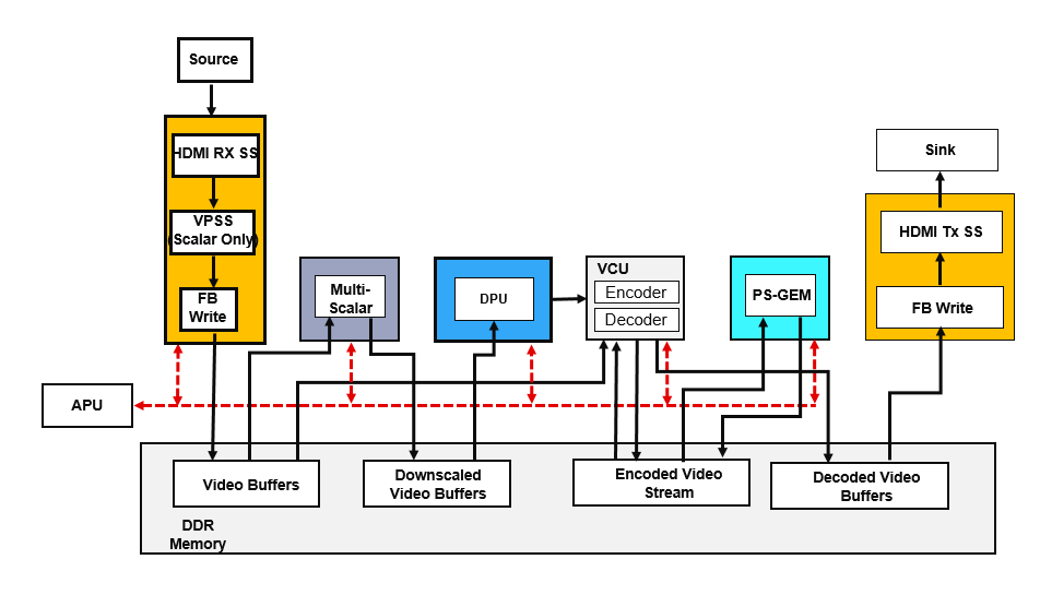
The below figure shows the Processing System (PS) and Programmable Logic (PL) components in this TRD. All PL components are in gray color.

This design supports the following video interfaces:
Sources:
HDMI-Rx capture pipeline implemented in the PL
File source (SD card, USB storage, SATA hard disk)
Stream-In from network or internet
Sinks:
HDMI-Tx display pipeline implemented in the PL
Stream-out on network or internet
VCU Codec:
Video Encoder/Decoder capability using VCU hard block in PL
H.264/H.265 encoding
Encoder/decoder parameter configuration using OMX interface
DPU:
DPU IP version 1.0
DNNDK version 2.08
Required DNNDK libraries are downloaded from AI Developer hub
Streaming Interfaces:
1G Ethernet PS GEM
Video format:
NV12
Supported Resolution:
4kp30
1080p30
1.3 VCU ROI Software
1.3.1 GStreamer Pipeline
The GStreamer plugin demonstrates the DPU capabilities with Xilinx VCU encoder’s ROI(Region Of Interest) feature. The plugin will detect ROI(face co-ordinates) from input frames using DPU IP and pass the detected ROI information to the Xilinx VCU encoder. The following figure shows the data flow for GStreamer pipeline of stream-out use case.
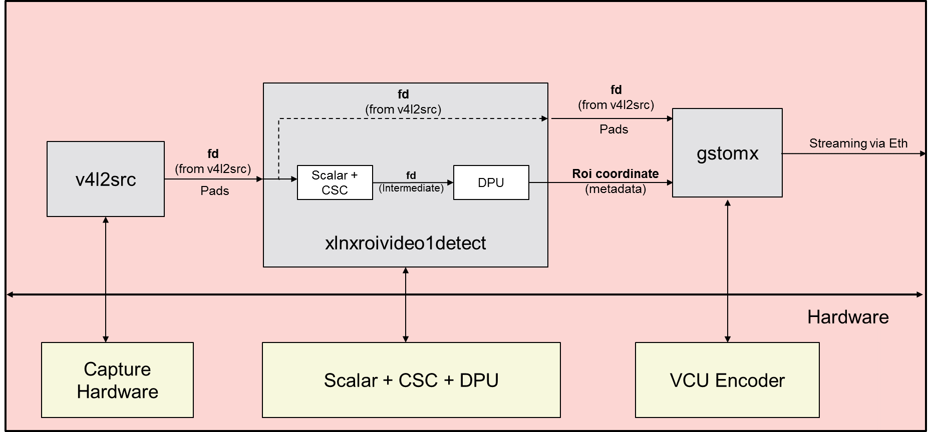
Block Diagram of Stream-out Pipeline
As shown in the above figure, the stream-out GStreamer pipeline performs the below list of operations:
v4l2src captures the data from HDMI-Rx in NV12 format and pass to xlnxroivideo1detect GStreamer plugin
xlnxroivideo1detect GStreamer plugin will scale down to 640x480 resolution and convert the data into BGR format
640x480 BGR frame will be provided to DPU IP as an input to find ROI(face co-ordinates)
Extracted ROI information will be passed to VCU encoder
The encoder will encode the input data by encoding ROI regions with high quality as compared to non-ROI region using received ROI information
Stream-out the encoded data using RTP protocol
The following figure shows the data flow for the GStreamer pipeline of stream-in use cases.
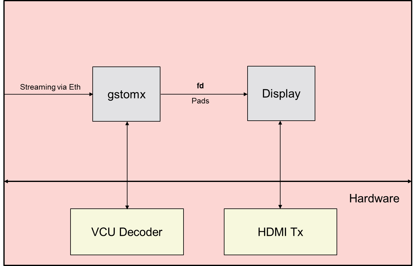
Block Diagram of Stream-in Pipeline
As shown in the above figure, the stream-in GStreamer pipeline performs the below list of operations:
Stream-in the encoded data using RTP protocol
The Xilinx VCU decoder will decode the data
Display the decoded data on HDMI-Tx display
The below figure shows the xlnxroivideo1detect GStreamer plugin data flow.

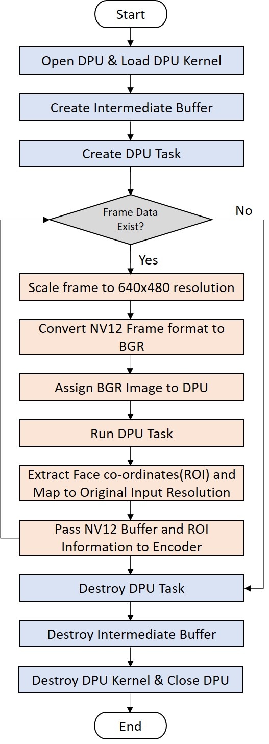
As shown in the above figure, our xlnxroivideo1detect GStreamer plugin will perform below the list of operations:
DPU is initialized and DPU kernel will be loaded using libn2cube APIs - int dpuOpen(), DPUKernel *dpuLoadKernel(const char *networkName)
DPU GStreamer plugin receives the data frame from HDMI-Rx through a v4l2src plugin
Create the DPU task - int dpuCreateTask(DPUKernel *kernel, int mode)
Scale the input frame to 640x480 resolution using Xilinx Scaler IP
Convert the input frame data format from NV12 to BGR format using Xilinx Color Space Converter(CSC) soft IP
Prepare the OpenCV image using BGR data
Pass the intermediate OpenCV image to the DPU - int dpuSetInputImage2(DPUTask *task, const char *nodeName, const cv::Mat &image, int idx=0)
Run the DPU task - int dpuRunTask(DPUTask *task)
Extract the ROI(face) co-ordinates from the DPU output
Map the detected face co-ordinates to the original input frame resolution
Fill the ROI metadata buffer using extracted ROI (face) co-ordinates
Pass the ROI metadata buffer and input NV12 frame data buffer to the Xilinx VCU encoder
Destroy the DPU task and kernel - int dpuDestroyTask(DPUTask *task), int dpuDestroyKernel(DPUKernel*kernel)
Close the DPU - int dpuClose()
1.3.2 Deep Learning Processor Unit(DPU)
DPU is a programmable engine dedicated to the convolutional neural network. The unit contains a register configure the module, data controller module, and convolution computing module. There is a specialized instruction set for DPU, which enables DPU to work efficiently for many convolutional neural networks. The deployed convolutional neural network in DPU includes VGG, ResNet, GoogLeNet, YOLO, SSD, MobileNet, FPN, etc.

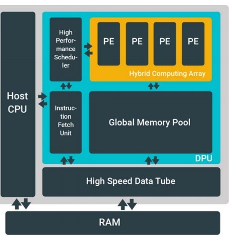
To use DPU, you should prepare the instructions and input image data in the specific memory address that DPU can access. The DPU operation also requires the application processing unit (APU) to service interrupts to coordinate data transfer. The DPU operation also requires the application processing unit (APU) to service interrupts to coordinate data transfer.
Refer to DPU IP PG338 to know more details on DPU.
The following figure shows the sequence of operations performed on the DPU device.

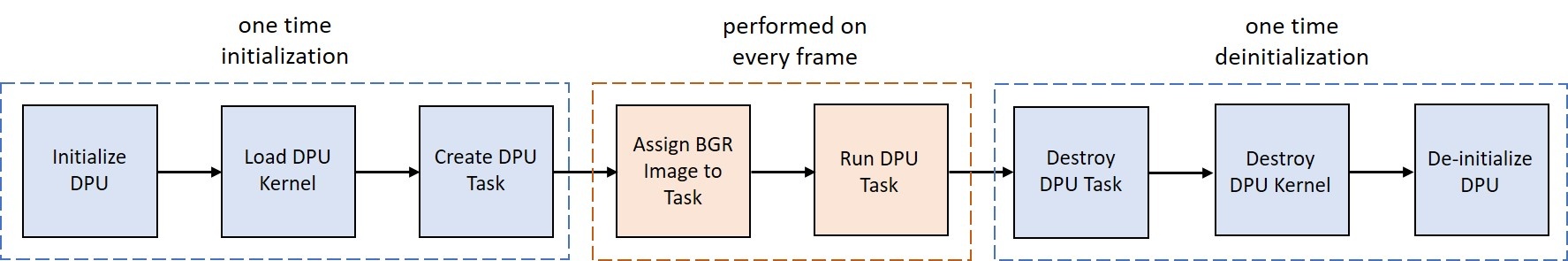
The libn2cube and, libdputils and libhineon from DNNDK are used to run face detection use case on DPU device. The GStreamer plugin uses the libn2cube library APIs to load the DPU kernel code and data into the DPU dedicated memory, create and run the DPU tasks.
The following sequence of steps are performed to access and run face detection using the DPU device:
DPU device is initialized by calling dpuOpen() API
From hybrid executable, load the DPU kernel including DPU instructions, weights and biases for specified neural network into dedicated DPU memory space
Instantiate a DPU Task from DPU Kernel and allocate corresponding DPU memory buffer
Set the input image to created DPU task using dpuSetInputImage2() API of libdputils
Run the DPU task to find the faces from the input image
Free the DPU dedicated memory used by the loaded kernel using
DPU device is uninitialized using dpuClose() API of libn2cube
1.3.3 DNNDK Overview
Deep Neural Network Development Kit (DNNDK) is a full-stack deep learning SDK for the Deep-learning Processor Unit(DPU). It provides a unified solution for deep neural network inference applications by providing pruning, quantization, compilation, optimization, and run-time support.
The below figure shows the data flow starting from training Machine Learning(ML) model to perform inference using DPU.


Below is the sequence of processes executed to run inference on DPU.
Machine Learning(ML) model is trained using Caffe or TensorFlow ML framework on input training data set
Compression will be performed on the trained model to get high throughput by reducing the memory bandwidth requirement
Deep Compression Tool (DECENT) provided by DNNDK is used to perform the compression process
The trained model is analyzed and pruning will be performed to remove the ineffective or very less effective nodes from the model
Quantization will be performed to reduce the computing complexity without losing prediction accuracy by converting 32-bit floating-point weights and activation values to an 8-bit integer
Deep Neural Network Compiler (DNNC) is used to perform model compression which maps the model to the DPU instructions
The front-end parser is responsible for parsing the Caffe/TensorFlow model and generates an intermediate representation (IR) of the input model
The optimizer handles optimizations based on the IR
The code generator maps the optimized IR to DPU instructions
The Deep Neural Network Assembler (DNNAS) is responsible for assembling DPU instructions into ELF binary code
The DPU loader handles the transfer of DPU kernels from the hybrid ELF executable into memory and dynamically relocates the memory of DPU code
The libn2cube library provides APIs to load the DPU kernel code and data into the DPU dedicated memory, create and run the DPU tasks
DPU drivers are provided by the DNNDK to interact with DPU hardware
DSight is the DNNDK performance profiling tool. It is a visual performance analysis tool for neural network model profiling
DExplorer tool provides DPU information like DPU running mode configuration, DPU status checking, DPU architecture version, DNNDK version, working frequency, DPU core numbers, etc.
Refer DNNDK user guide to know more details on DNNDK.
1.4 Software Tools and System Requirements
Hardware
Required:
ZCU106 evaluation board (rev C/D/E/F/1.0) with power cable
Monitor with HDMI input supporting 3840x2160 resolution or 1920x1080 resolution
HDMI cable 2.0 certified
Class-10 SD card
Ethernet cable
Optional:
USB pen drive formatted with the FAT32 file system and hub
SATA drive formatted with the FAT32 file system, external power supply, and data cable
Software Tools
Required:
Linux host machine for all tool flow tutorials (see UG1144 for detailed OS requirements)
PetaLinux Tools version 2019.2 (see UG1144 for installation instructions)
Vivado Design suite version 2019.2
Git a distributed version control system
Serial terminal emulator e.g. teraterm
Compatibility
The reference design has been tested successfully with the following user-supplied components.
HDMI Monitor:
Make/Model | Resolutions |
|---|---|
LG 27UD88 | 3840 x 2160 @ 30Hz |
Philips BDM4350UC | 3840 x 2160 @ 60Hz |
Dell-p2417h | 1920 x 1080 @ 60Hz |
BenQ - EW3270-T | 3840 x 2160 @ 60Hz |
Cable:
HDMI 2.0 compatible cable
The below table provides the performance information:
Resolution | FPS Achieved |
|---|---|
4kp30 | 22 - 25 |
1080p30 | 30 |
1.5 Board Setup
The below section will provide the information on the ZCU106 board setup for running ROI design.
Connect the Micro USB cable into the ZCU106 Board Micro USB port J83, and the other end into an open USB port on the host PC. This cable is used for UART over USB communication.
Insert the SD card with the images copied into the SD card slot J100. Please find here how to prepare the SD card for a specific design.
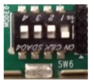
Set the SW6 switches as shown in the below Figure. This configures the boot settings to boot from SD.
Connect one end of HDMI cable to the board’s P7 stacked HDMI connector (upper port) and another end to the HDMI monitor.
For a USB storage device, connect the USB hub along with the mouse. (Optional)
For SATA storage device, connect SATA data cable to SATA 3.0 port. (Optional).
Set up a terminal session between a PC COM port and the serial port on the evaluation board (See the Determine which COM to use to access the USB serial port on the ZCU106 board for more details).
Copy the VCU-ROI images into the SD card and insert the SD card on the board.
The below images will show how to connect interfaces on the ZCU106 board.
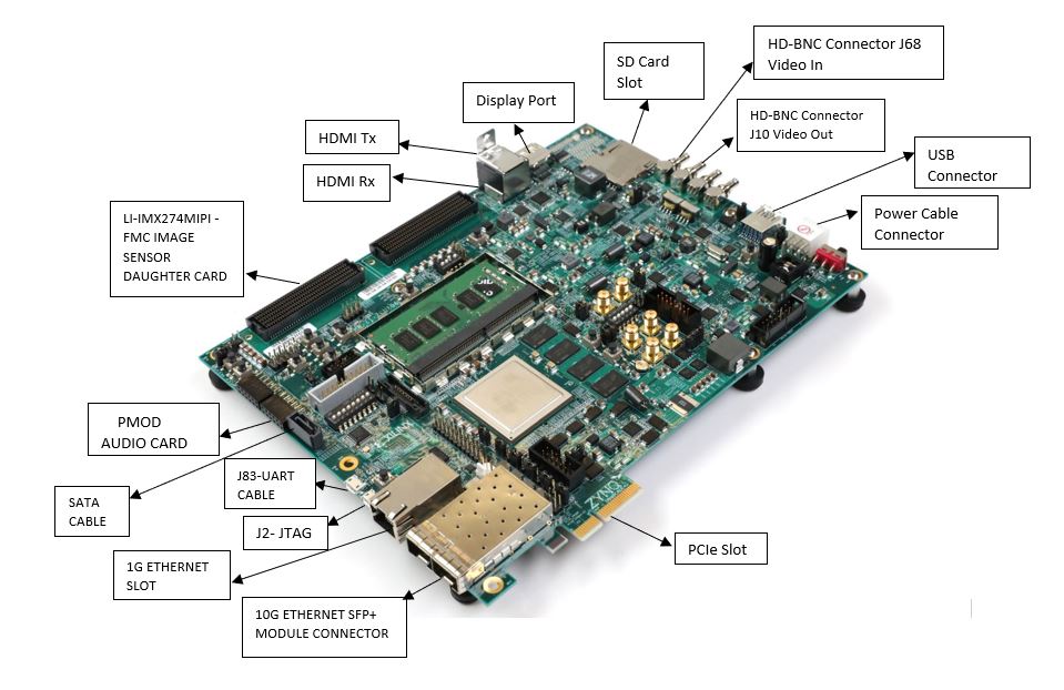
The above figure shows all the zcu106 board connector slots
1.6 Run Flow
The VCU ROI TRD package is released with the source code, Vivado project, Petalinux BSP, and SD card image that enables the user to run the demonstration. It also includes the binaries necessary to configure and boot the ZCU106 board. Prior to running the steps mentioned in this wiki page, download the VCU ROI TRD package and extract its contents to a directory referred to as ‘TRD_HOME' which is the home directory.
Refer below link to download the VCU ROI TRD package.
Prepare the SD card. Use the SD Card Formatter tool to format the SD card, https://www.sdcard.org/downloads/formatter_4/
TRD package contents are placed in the following directory structure. The user needs to copy all the files from the 4 to boot partition of FAT32 formatted SD card directory.
| Code Block |
|---|
└── vcu_roi_2019.2_v1.0 ├── apu │ └── vcu_petalinux_bsp │ └── xilinx-vcu-roi-zcu106-v2019.2-final.bsp ├── images │ └── vcu_roi │ ├── autostart.sh │ ├── bin │ ├── BOOT.BIN │ ├── config │ ├── export.sh │ ├── image.ub │ ├── libdpumodeldensebox.so │ ├── system.dtb │ └── vcu ├── pl │ ├── constrs │ │ ├── vcu_trd_async.xdc │ │ └── vcu_trd.xdc │ ├── designs │ │ └── zcu106_dpu_hdmi │ ├── prebuild │ │ └── zcu106_dpu_hdmi_wrapper.xsa │ ├── README.md │ └── srcs │ ├── hdl │ ├── ip │ └── top └── README.txt |
The below snippet shows the configuration files(input.cfg) for running various Display, and Streaming use cases. All these configurations files are placed in the $TRD_HOME/images/vcu_roi/config directory.
| Code Block |
|---|
└── config ├── 1080p30 │ ├── Display │ ├── Record │ ├── Stream-in │ └── Stream-out ├── 4kp30 │ ├── Display │ ├── Record │ ├── Stream-in │ └── Stream-out └── input.cfg |
Boot the board with Flash SD Card with VCU ROI images
1.6.1 GStreamer Application (vcu_gst_app)
The vcu_gst_app is a command-line multi-threaded Linux application. The command-line application requires an input configuration file (input.cfg) to be provided in the plain text.
After the board gets booted, the display screen turns to the blue screen; which means it is ready to test. Otherwise before the execution of vcu_gst_app, manually run below modetest command to set CRTC configurations.
Modetest commands:
for 4k Resolution:
Code Block % modetest -D a0060000.v_mix -s 35:3840x2160-30@BG24
For 1080p Resolution:
Code Block % modetest -D a0060000.v_mix -s 35:1920x1080-30@BG24
Note: Make sure that you have executed “source /media/card/export.sh” command before running the DPU use case.
Execution of the application is shown below:
| Code Block | ||
|---|---|---|
| ||
% source /media/card/export.sh % vcu_gst_app <path to *.cfg file> |
Notes for gst-launch-1.0 commands: Refer xmedia-ctl commands
Display: Capture --> (ROI) --> Encode --> Decode --> Display
4kp30 HEVC Display Pipeline execution using vcu_gst_app
Code Block % vcu_gst_app /media/card/config/4kp30/Display/Single_4kp30_HEVC_5Mbps.cfg
Run the following gst-launch-1.0 command to display processed pipeline (capture → roi_plugin → encode → decode → display) on HDMI-Tx.
Code Block language bash $ gst-launch-1.0 v4l2src device=/dev/video0 io-mode=4 ! video/x-raw, width=3840, height=2160, format=NV12, framerate=30/1 ! xlnxroivideo1detect capture-io-mode=4 output-io-mode=5 ! omxh265enc qp-mode=roi num-slices=8 prefetch-buffer=true gop-length=60 periodicity-idr=270 control-rate=low-latency target-bitrate=5000 gop-mode=low-delay-p cpb-size=200 initial-delay=100 filler-data=false min-qp=15 max-qp=40 b-frames=0 low-bandwidth=false ! video/x-h265, profile=main, alignment=au ! queue ! omxh265dec internal-entropy-buffers=5 low-latency=0 ! queue max-size-bytes=0 ! fpsdisplaysink text-overlay=false video-sink="kmssink bus-id="a0060000.v_mix""
Record: Capture --> (ROI) --> Encode --> Filesink
4kp30 HEVC Record Pipeline execution using vcu_gst_app
Code Block % vcu_gst_app /media/card/config/4kp30/Record/Single_4kp30_HEVC_5Mbps.cfg
Run the following gst-launch-1.0 command to record video using GStreamer pipeline.
Code Block $ gst-launch-1.0 v4l2src device=/dev/video0 io-mode=4 ! video/x-raw, format=NV12,width=3840,height=2160,framerate=30/1 ! xlnxroivideo1detect capture-io-mode=4 output-io-mode=5 ! omxh265enc qp-mode=roi num-slices=8 prefetch-buffer=true gop-length=60 periodicity-idr=270 control-rate=low-latency target-bitrate=5000 gop-mode=low-delay-p cpb-size=200 initial-delay=100 filler-data=false min-qp=15 max-qp=40 b-frames=0 low-bandwidth=false ! video/x-h265, profile=main, alignment=au ! queue ! video/x-h265, profile=main, alignment=au ! mpegtsmux alignment=7 name=mux ! filesink location="/run/media/sda/test.ts"
Note: File location should be SATA SSD(ext4 format) to avoid the read-write bandwidth issue.
File Playback: File_source --> Decode --> Display
Run the following gst-launch-1.0 command to play the recorded file on HDMI-Tx using the GStreamer pipeline.
Code Block $ gst-launch-1.0 uridecodebin uri="file:///run/media/sda/test.ts" ! queue max-size-bytes=0 ! kmssink bus-id="a0060000.v_mix"
Note: File location should be SATA SSD(ext4 format) to avoid the read-write bandwidth issue.
Stream-out: ( Server )
Set IP address for server:
Code Block % ifconfig eth0 192.168.25.90
4kp30 HEVC Stream-out Pipeline execution using vcu_gst_app
Code Block % vcu_gst_app /media/card/config/4kp30/Stream-out/Single_4kp30_HEVC_5Mbps.cfg
Run the following gst-launch-1.0 command for low-latency stream-out pipeline.
Code Block $ gst-launch-1.0 v4l2src device=/dev/video0 io-mode=4 ! video/x-raw, format=NV12, width=3840, height=2160, framerate=30/1 ! xlnxroivideo1detect capture-io-mode=4 output-io-mode=5 ! omxh265enc qp-mode=roi num-slices=8 prefetch-buffer=true gop-length=60 periodicity-idr=270 control-rate=low-latency target-bitrate=5000 gop-mode=low-delay-p cpb-size=200 initial-delay=100 filler-data=false min-qp=15 max-qp=40 b-frames=0 low-bandwidth=false ! video/x-h265, profile=main, alignment=au ! queue ! mpegtsmux alignment=7 name=mux ! rtpmp2tpay ! udpsink host=192.168.25.89 port=5004
Note: Here 192.168.25.89 is host/client IP address and 5004 is port no.
Stream-in: ( Client )
Apply modetest command as per resolution: Refer 4kp30, 1080p30
Set IP address for the client:
Code Block % ifconfig eth0 192.168.25.89
4kp30 HEVC Stream-in Pipeline execution using vcu_gst_app
Code Block % vcu_gst_app /media/card/config/4kp30/Stream-in/input.cfg
Run the following gst-launch-1.0 command to display low-latency stream-in on HDMI-Tx video using the Gstreamer pipeline where 5004 is port no.
Code Block $ gst-launch-1.0 udpsrc port=5004 buffer-size=60000000 caps="application/x-rtp, clock-rate=90000" ! rtpjitterbuffer latency=1000 ! rtpmp2tdepay ! tsparse ! video/mpegts ! tsdemux name=demux ! queue ! h265parse ! video/x-h265, profile=main, alignment=au ! omxh265dec internal-entropy-buffers=5 low-latency=0 ! queue max-size-bytes=0 ! kmssink bus-id="a0060000.v_mix"
NOTE: Make sure HDMI-Rx should be configured to 4kp30 mode.
1.7 Build Flow
Refer below link to download the VCU ROI TRD package.
Unzip the released package.
| Code Block |
|---|
% unzip </path/to/downloaded/zipfile>/vcu_roi_2019.2_v1.0.zip |
The following tutorials assume that the $TRD_HOME environment variable is set as given below.
| Code Block |
|---|
% export TRD_HOME=</path/to/downloaded/zipfile>/vcu_roi_2019.2_v1.0 |
1.7.1 HW build Flow
This tutorial shows how to build the hardware and generating XSA using the Vivado tool. Refer to the vivado-release-notes-install-license(UG973) for installation.
Open a Linux terminal
Change directory to $TRD_HOME/pl folder
Run the following command in Vivado tcl shell to create the Vivado IPI project and invoke the GUI
Code Block % vivado -source ./designs/zcu106_dpu_hdmi/project.tcl
After executing the script, the Vivado IPI block design comes up.
Click on “Generate Bitstream”
Note: If the user gets any pop-up with “No implementation Results available”. Click “Yes”. Then, if any pop-up comes up with “Launch runs”, Click "OK”.
The design is implemented, and a pop-up window comes up saying “Open Implemented Design”. Click "OK" to open the Implemented design
Go to File > Export > Export Hardware
In the Export Hardware Platform for SDK window select "Include bitstream" and click "OK"
By default, the XSA is created at pl/prebuild/zcu106_dpu_hdmi_wrapper.xsa
1.7.2 Petalinux build Flow
This tutorial shows how to build the Linux image and boot image using the PetaLinux build tool.
PetaLinux Installation: Refer to the PetaLinux Tools Documentation (UG1144) for installation.
NOTE: It is recommended to follow the build steps in sequence.
Source Petalinux settings.sh
Code Block % bash % source <path/to/petalinux-installer>/tool/petalinux-v2019.2-final/settings.sh
Create PetaLinux project
Code Block % cd $TRD_HOME/apu/vcu_petalinux_bsp % petalinux-create -t project -s xilinx-vcu-roi-zcu106-v2019.2-final.bsp
Configure the PetaLinux project
Code Block % cd xilinx-vcu-roi-zcu106-v2019.2-final % petalinux-config --get-hw-description=<Path to directory of XSA>
For e.g.
Code Block % petalinux-config --get-hw-description=$TRD_HOME/pl/prebuild
Note: Hardware configuration will create a pop-up window with settings; Save & Exit
Create a soft link of design dtsi file to system-user.dtsi using below command
Code Block % cd project-spec/meta-user/recipes-bsp/device-tree/files % ln -sf vcu_roi.dtsi system-user.dtsi % cd $TRD_HOME/apu/vcu_petalinux_bsp/xilinx-vcu-roi-zcu106-v2019.2-final
Build the PetaLinux project
Code Block % petalinux-build
Create a boot image (BOOT.BIN) including FSBL, ATF, bitstream, and u-boot
Code Block % cd images/linux % petalinux-package --boot --fsbl zynqmp_fsbl.elf --fpga system.bit --u-boot --pmufw pmufw.elf
Copy the generated boot image and Linux image to the SD card directory (vcu_roi_2019.2_v1.0/images/vcu_roi)
| Code Block |
|---|
% cp BOOT.BIN image.ub <image directory> |
For e.g.
| Code Block |
|---|
% cp BOOT.BIN image.ub $TRD_HOME/images |
1.8 VCU GST APP
The vcu_gst_app and supporting libraries will be built as a "vcu-gst-app" recipe inside petalinux-project. Refer "project-spec/meta-user/recipes-apps/vcu-gst-app" directory inside petalinux-project for vcu-gst-app recipe. Source of vcu_apm_lib, vcu_video_lib, vcu_gst_lib and vcu_gst_app is provided as zip inside "project-spec/meta-user/recipes-apps/vcu-gst-app/files/" directory. vcu_gst_app will be built as part of petalinux project and the executable is placed in /usr/bin location of rootfs. Users can update the zip file if any source code modifications need to be and run following command to build vcu-gst-app recipe.
| Code Block | ||
|---|---|---|
| ||
% petalinux-build -c vcu-gst-app |
Note:
Modify the value of the Enable Roi parameter to FALSE in the input.cfg file to run the pipeline without ROI.
Able to get 23 FPS with 4kp30 and 30 FPS with 1080p30.
60 FPS pipelines are supported, but FPS drops are observed.
Run time enablement/disablement of ROI is not supported.
2 Other Information
2.1 Known Issues
For Petalinux related known issues please refer AR# 72950: PetaLinux 2019.2 - Product Update Release Notes and Known Issues.
For VCU related known issues please refer AR# 66763: LogiCORE H.264/H.265 Video Codec Unit (VCU) - Release Notes and Known Issues and Xilinx Zynq UltraScale+ MPSoC Video Codec Unit.
2.2 Limitations
For Petalinux related limitations please refer AR# 72950: PetaLinux 2019.2 - Product Update Release Notes and Known Issues.
For VCU related limitations please refer AR# 66763: LogiCORE H.264/H.265 Video Codec Unit (VCU) - Release Notes and Known Issues, Xilinx Zynq UltraScale+ MPSoC Video Codec Unit and PG252 link.
2.3 Optimum VCU Encoder parameters for use-cases
Video streaming:
Video streaming use-case requires a very stable bitrate graph for all pictures
It is good to avoid periodic large Intra pictures during the encoding session
Low-latency rate control (hardware RC) is the preferred control-rate for video streaming, it tries to maintain equal amount frame sizes for all pictures
Good to avoid periodic Intra frames instead use low-delay-p (IPPPPP…)
VBR is not a preferred mode of streaming
Performance: AVC Encoder settings:
It is preferred to use 8 or higher slices for better AVC encoder performance
AVC standard does not support Tile mode processing which results in the processing of MB rows sequentially for entropy coding
Quality: Low bitrate AVC encoding:
Enable profile=high and use qp-mode=auto for low-bitrate encoding use-cases
The high profile enables 8x8 transform which results in better video quality at low bitrates
3 Appendix A - Input Configuration File (input.cfg)
The example configuration files are stored at /media/card/config/ folder.
Common Configuration:
It is the starting point of a common configuration.
Num of Input:
Provide the number of inputs. It will be 1 only due to single-stream support
Options: 1
Output:
Select the video interface.
Options: HDMI
Out Type:
Options: display, record, and stream
Display Rate:
Pipeline frame rate.
Options: 30 FPS
Exit:
It indicates to the application that the configuration is over.
Input Configuration:
It is the starting point of the input configuration.
Input Num:
Starting Nth input configuration.
Options: 1
Input Type:
Input source type.
Options: HDMI, File, Stream
Uri:
File path or Network URL. Applicable for file playback and stream-in pipeline only. Supported file formats for playback are ts, mp4, and mkv.
Options: file:///run/media/sda/test_1.ts (for file path), udp://192.168.25.89:5004/ (for Network streaming, here 192.168.25.89 is IP address and 5004 is port no)
Raw:
To tell the pipeline is processed. Pass-through is not supported.
Options: False
Width:
The width of the live source.
Options: 3840, 1920
Height:
The height of the live source.
Options: 2160, 1080
Enable Roi:
Enable or Disable ROI in the pipeline.
Options: True, False
Exit:
It indicates to the application that the configuration is over.
Encoder Configuration:
It is the starting point of encoder configuration.
Encoder Num:
Starting Nth encoder configuration.
Options: 1
Encoder Name:
Name of the encoder.
Options: AVC, HEVC
Profile:
Name of the profile.
Options: baseline, main or high for AVC. Main for HEVC
Rate Control:
Rate control options.
Options: CBR, low-latency
Filler Data:
Options: False
QP:
QP control mode used by the VCU encoder.
Options: Uniform, Auto
L2 Cache:
Enable or Disable L2Cache buffer in the encoding process.
Options: True, False
Latency Mode:
Encoder latency mode.
Options: Normal, sub_frame
Low Bandwidth:
If enabled, decrease the vertical search range used for P-frame motion estimation to reduce the bandwidth.
Options: True, False
Gop Mode:
Group of Pictures mode.
Options: Basic, low_delay_p
Bitrate:
Target bitrate in Kbps
Options: 1-5000
B Frames:
Number of B-frames between two consecutive P-frames
Options: 0-4
Slice:
The number of slices produced for each frame. Each slice contains one or more complete macroblock/CTU row(s). Slices are distributed over the frame as regularly as possible. If slice-size is defined as well more slices may be produced to fit the slice-size requirement.
Options:
4-22 4kp resolution with HEVC codec
4-32 4kp resolution with AVC codec
4-32 1080p resolution with HEVC codec
4-32 1080p resolution with AVC codec
GoP Length:
The distance between two consecutive I frames
Options: 1-1000
Format:
The format of input data.
Options: NV12
Preset:
Options: custom
Exit
It indicates to the application that the configuration is over.
Record Configuration:
It is the starting point of record configuration.
Record Num:
Starting Nth record configuration.
Options: 1
Out-File Name:
Record file path.
Options: /run/media/sda/test_1.ts
Duration:
Duration in minutes.
Options: 1-3
Exit
It indicates to the application that the configuration is over.
Streaming Configuration:
It is the starting point of streaming configuration.
Streaming Num:
Starting Nth Streaming configuration.
Options: 1
Host IP:
The host to send the packets to
Options: 192.168.25.89 or Windows PC IP
Port:
The port to send the packets to
Options: 5004
Exit
It indicates to the application that the configuration is over.
Trace Configuration:
It is the starting point of trace configuration.
FPS Info:
To display fps info on the console.
Options: True, False
APM Info:
To display the APM counter number on the console.
Options: True, False
Pipeline Info:
To display pipeline info on the console.
Options: True, False
Loop Playback:
To play display pipeline in the loop.
Options: True, False
Loop Interval:
To repeat the playback of the display pipeline after a specific time duration. The default is False.
Options: 5 - 10 sec
Exit
It indicates to the application that the configuration is over.
4 Appendix B
HDMI source can be locked to any resolution. Run the below command for all media nodes to print media device topology. In the topology log, look for the “v_hdmi_rx_ss” string to identify the HDMI input source media node.
Code Block $ xmedia-ctl -p -d /dev/media0
To check the link status, resolution and video node of the HDMI input source, run below xmedia-ctl command.
Code Block $ xmedia-ctl -p -d /dev/media0
When HDMI source is connected to 4KP30 resolution, it shows:
| Code Block |
|---|
root@zcu106_vcu_trd:/media/card# xmedia-ctl -p -d /dev/media0
Media controller API version 4.19.0

Media device information
------------------------
driver          xilinx-video
model           Xilinx Video Composite Device
serial
bus info
hw revision     0x0
driver version  4.19.0

Device topology
- entity 1: vcap_hdmi output 0 (1 pad, 1 link)
            type Node subtype V4L flags 0
            device node name /dev/video0 -----> Video node for HDMI Rx source
        pad0: Sink
                <- "a0080000.v_proc_ss":1 [ENABLED]

- entity 5: a0080000.v_proc_ss (2 pads, 2 links)
            type V4L2 subdev subtype Unknown flags 0
            device node name /dev/v4l-subdev0
        pad0: Sink
                [fmt:RBG888_1X24/3840x2160 field:none]
                <- "a0050000.v_hdmi_rx_ss":0 [ENABLED]
        pad1: Source
                [fmt:VYYUYY8_1X24/3840x2160 field:none]
                -> "vcap_hdmi output 0":0 [ENABLED]

- entity 8: a0050000.v_hdmi_rx_ss (1 pad, 1 link)
            type V4L2 subdev subtype Unknown flags 0
            device node name /dev/v4l-subdev1
        pad0: Source
                [fmt:RBG888_1X24/3840x2160 field:none colorspace:srgb]
                [dv.caps:BT.656/1120 min:0x0@25000000 max:4096x2160@297000000 stds:CEA-861,DMT,CVT,GTF caps:progressive,reduced-blanking,custom]
                [dv.detect:BT.656/1120 3840x2160p30 (4400x2250) stds:CEA-861 flags:CE-video] -----> Resolution and Frame-rate of HDMI Rx source
-> "a0080000.v_proc_ss":0 [ENABLED] |
NOTE: Check resolution and frame-rate of "dv.detect" under "v_hdmi_rx_ss" node.
When the HDMI source is not connected, it shows:
| Code Block | ||
|---|---|---|
| ||
root@zcu106_vcu_trd:/media/card# xmedia-ctl -p -d /dev/media0
Media controller API version 4.19.0

Media device information
------------------------
driver          xilinx-video
model           Xilinx Video Composite Device
serial
bus info
hw revision     0x0
driver version  4.19.0

Device topology
- entity 1: vcap_hdmi output 0 (1 pad, 1 link)
            type Node subtype V4L flags 0
            device node name /dev/video0 -----> Video node for HDMI Rx source
        pad0: Sink
                <- "a0080000.v_proc_ss":1 [ENABLED]

- entity 5: a0080000.v_proc_ss (2 pads, 2 links)
            type V4L2 subdev subtype Unknown flags 0
            device node name /dev/v4l-subdev0
        pad0: Sink
                [fmt:RBG888_1X24/3840x2160 field:none]
                <- "a0050000.v_hdmi_rx_ss":0 [ENABLED]
        pad1: Source
                [ fmt:VYYUYY8_1X24/3840x2160 field:none]
                -> "vcap_hdmi output 0":0 [ENABLED]

- entity 8: a0050000.v_hdmi_rx_ss (1 pad, 1 link)
            type V4L2 subdev subtype Unknown flags 0
            device node name /dev/v4l-subdev1
        pad0: Source
                [fmt:RBG888_1X24/3840x2160 field:none colorspace:srgb]
                [dv.caps:BT.656/1120 min:0x0@25000000 max:4096x2160@297000000 stds:CEA-861,DMT,CVT,GTF caps:progressive,reduced-blanking,custom]
                [dv.query:no-link] -----> HDMI Rx Link Status
-> "a0080000.v_proc_ss":0 [ENABLED] |
NOTE: Here "dv.query:no-link" under "v_hdmi_rx_ss" node shows HDMI-Rx source is not connected or HDMI-Rx source is not active(Try waking up the device by pressing a key on remote).
Notes for gst-launch-1.0 commands:
Video node for HDMI Rx source can be checked using xmedia-ctl command. Run below xmedia-ctl command to check video node for HDMI Rx.
| Code Block |
|---|
% xmedia-ctl -p -d /dev/media0 |
Make sure the HDMI-Rx media pipeline is configured for 4kp30 resolution and source/sink has the same color format. Run below xmedia-ctl commands to set the resolution and format of the HDMI scaler node.
When HDMI Input Source is NVIDIA SHIELD
| Code Block |
|---|
$ xmedia-ctl -d /dev/media0 -V "\"a0080000.v_proc_ss\":0 [fmt:RBG888_1X24/3840x2160 field:none]" $ xmedia-ctl -d /dev/media0 -V "\"a0080000.v_proc_ss\":1 [fmt:VYYUYY8_1X24/3840x2160 field:none]" |
Note: Make sure NVIDIA SHIELD is configured for 4kp resolution and RGB888 color format.
Follow the below steps to switch the HDMI-Rx resolution from 1080p30 to 4kp30.
Check current HDMI Input Source Resolution (1080p30) by following the above-mentioned steps.
Set below configurations in /media/card/input.cfg file for HDMI-1080p30.
| Code Block |
|---|
Common Configuration : START Num Of Input : 1 Output : HDMI Out Type : Display Frame Rate : 30 Exit Input Configuration : START Input Num : 1 Input Type : hdmi Raw : FALSE Width : 1920 Height : 1080 Enable Roi : TRUE Exit |
Run vcu_gst_app for current HDMI resolution (1080p30) by executing the following command.
Code Block language bash $ vcu_gst_app /media/card/config/input.cfg
Change Resolution of HDMI Input Source from 1080p30 to 4kp30 by following the below steps.
Set the HDMI source resolution to 4kp30 (Homepage → settings → display & sound → Advanced settings → HDMI settings → HDMI display modes → change to 4kp30)
Save the configuration to take place the change
Verify the desired HDMI Input Source Resolution (4kp30) by following the above-mentioned steps
If HDMI Tx link-up issue is observed after Linux booting, use the following command:
| Code Block |
|---|
$ modetest -D a0060000.v_mix -s 35:3840x2160-30@BG24 |
Run the following gst-launch-1.0 command to display a pass-through pipeline.
| Code Block |
|---|
$ gst-launch-1.0 v4l2src device=/dev/video0 io-mode=4 ! video/x-raw, width=3840, height=2160, format=NV12, framerate=30/1 ! queue ! kmssink bus-id="a0060000.v_mix" |
Run the following gst-launch-1.0 command to run the ROI use case in the RAW pipeline.
| Code Block |
|---|
$ gst-launch-1.0 v4l2src device=/dev/video0 io-mode=4 ! video/x-raw, width=3840, height=2160, format=NV12, framerate=30/1 ! xlnxroivideo1detect capture-io-mode=4 output-io-mode=5 ! kmssink bus-id="a0060000.v_mix" |