This page shows the following two examples:
- IPI messaging example from PMU to RPU
- IPI messaging example from RPU to PMU
Table of Contents
Requirements
- ZCU102 development board (This design example has been tested on silicon 4.0 rev1.0 board)
- SDK (2018.1 release)
IPI messaging example from PMU to RPU
This design example shows how to send IPI messages from PMU to RPU periodically. PMU Firmware can be configured to send IPI message to RPU for every 10 seconds. RPU can be configured to receive IPI messages from PMU. In this example, PMU sends IPI messages to RPU and waits for response. RPU, after receiving an IPI message will respond back to PMU with success.
Create and modify PMU Firmware
- Start Xilinx SDK 2018.1
- Go to File -> New -> Application Project
- Give a project name (Ex: pmu_firmware)
- Select Standalone in OS platform category. Select ZCU102_hw_platform(pre-defined) in Hardware Platform category. Select psu_pmu_0 in Processor category
- Click Next. Select ZynqMP PMU Firmware from available templates and click on Finish to create project
- Now download the zip file
| View file |
|---|
| name | pmu_ipi_example_src.zip |
|---|
|
, extract and add the source files to PMU Firmware code base, define ENABLE_SCHEDULER and XPFW_DEBUG_DETAILED build flags and build the PMU Firmware
Create FSBL application for RPU
- In SDK, go to File -> New -> Application Project
- Give a project name (Ex: fsbl_r5)
- Select psu_cortexr5_0 in Processor category
- Click Next. Select Zynq MP FSBL from available templates and click on Finish to create project
Create RPU application for IPI Example
- In SDK, go to File -> New -> Application Project
- Give a project name (Ex: ipi_example_app)
- Select psu_cortexr5_0 in Processor category
- Click Next. Select Empty Application from available templates and click on Finish to create project
- Download these source files
| View file |
|---|
| name | rpu_ipi_example_app_src.zip |
|---|
|
- Extract the zip file. The src/ directory contains the required files for this example. Add these files to the project. Set EXAMPLE_IPI_RECEIVE macro to 0x1U and EXAMPLE_IPI_SEND macro to 0x0U in default.h file
Steps to create boot image
- In SDK, go to Xilinx -> Create Boot Image. Create Boot Image window appears as below
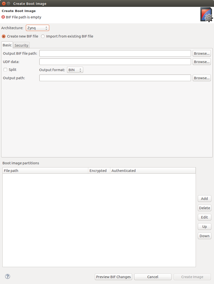
- Select Zynq MP in Architecture category. Select Create new BIF file option
- Browse and select path for Output BIF file path
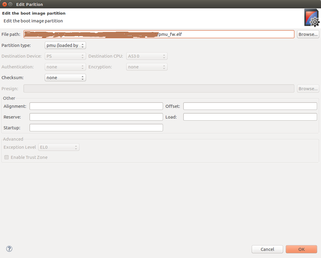
- Click on Add to add partitions. Select pmu_firmware executable path at File path. Select Partition type as pmu (loaded by bootrom) and click OK. Here, we are using loading of PMU Firmware by BOOT ROM option. User can also select loading of PMU Firmware by FSBL. For that, select Partion type as datafile and Destination CPU as RPU 0.
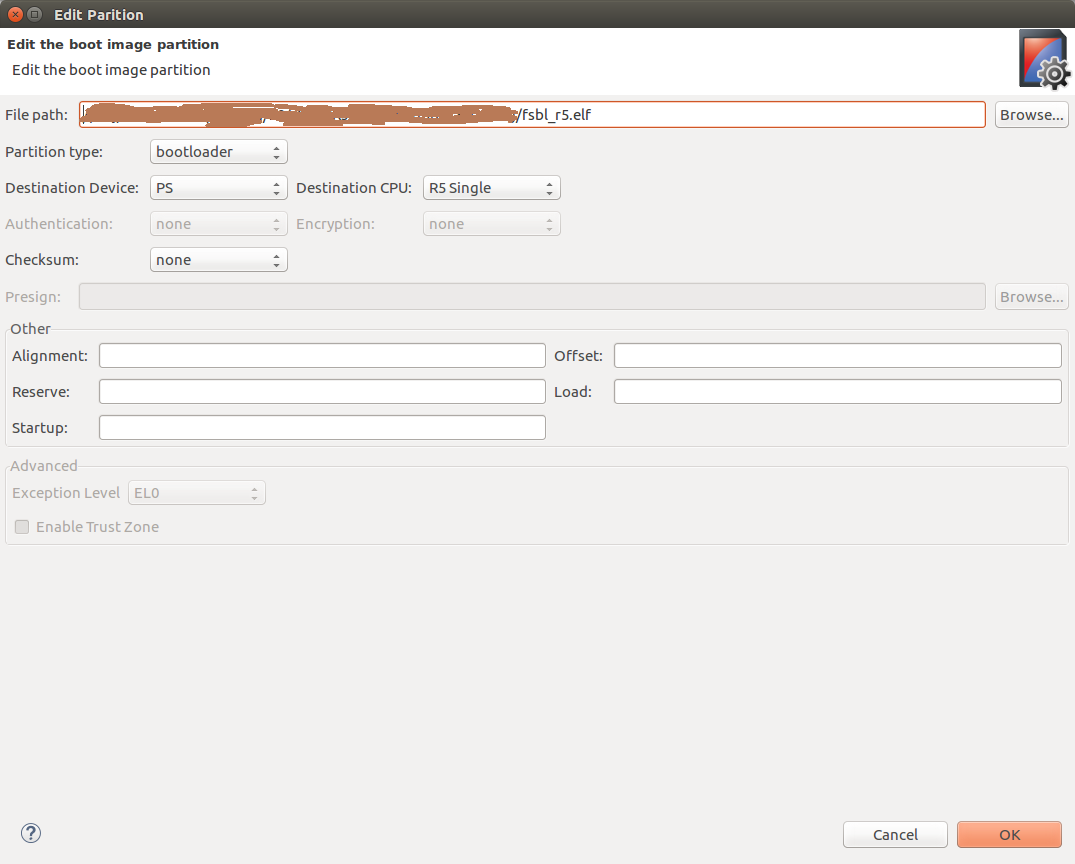
- Click on Add button again to add FSBL partition. Select fsbl_r5 executable path at File path. Select Partition type as bootloader, Destination Device as PS and Destination CPU as R5 Single. Click OK. Please see the below image for reference
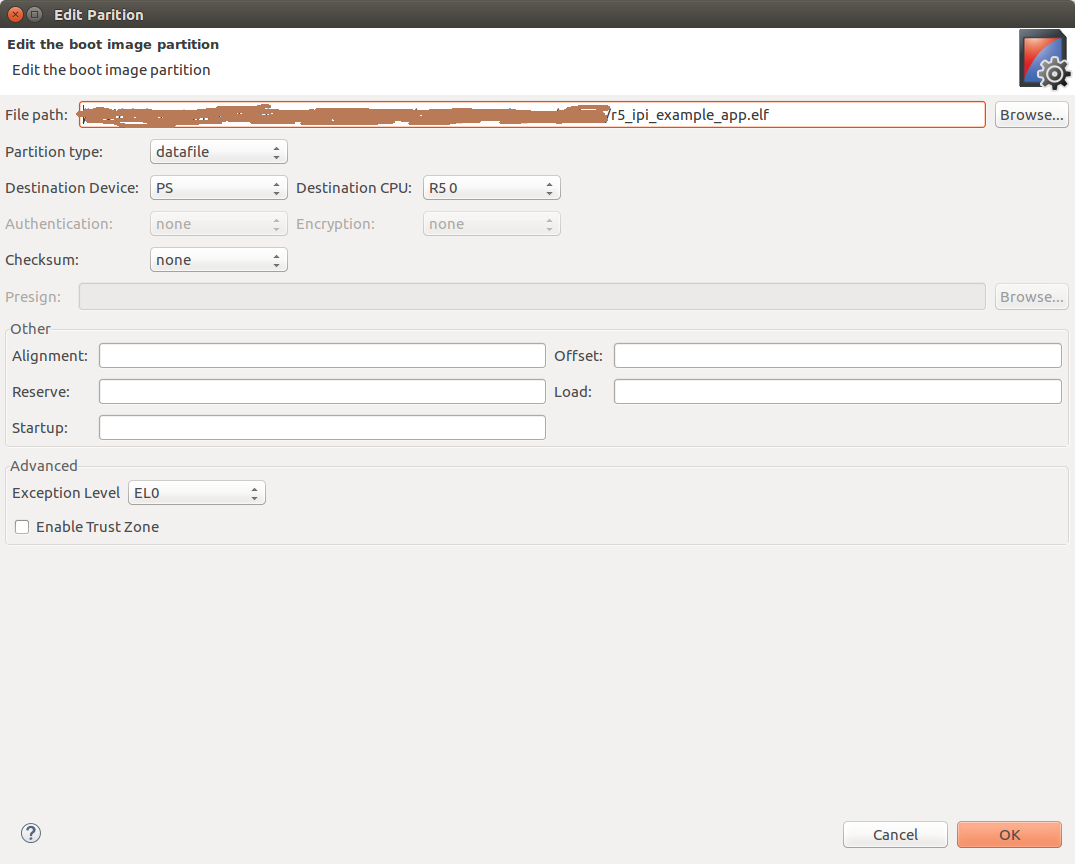
- Again, click on Add button to select IPI example application partition. Select ipi_example executable path at File path. Select Partition type as datafile, Destination Device as PS and Destination CPU as R5 0. Click OK. Please see the below image for reference
- Now click on Create Image. BOOT.BIN is created at Output BIF file path. Copy the BOOT.BIN to SD card and power-on ZCU102 board in SD boot mode. And observe prints on UART terminal
Snippet of BIF
Below is the snippet of BIF file created with the steps mentioned above
| Code Block |
|---|
|
//arch = zynqmp; split = false; format = BIN
the_ROM_image:
{
    [fsbl_config]r5_single
    [bootloader]C:\Images\fsbl_r5.elf
    [pmufw_image]C:\Images\pmu_fw.elf
    [destination_cpu = r5-0]C:\Images\r5_ipi_example_app.elf
}
|
Basic flow of execution
- PMU Firmware application runs on PMU Microblaze. It registers a module which schedules a task for sending an IPI message to RPU and registers an IPI handler to be called whenever an IPI message is triggered to this module
- R5 FSBL runs on R5 processor and hands-off to IPI Example application. RPU IPI example application initializes RPU GIC and connect IPI interrupt. It initializes IPI, enables IPI interrupt from PMU to RPU-0 and waits for IPI messages
- PMU Firmware sends an IPI message with message number to RPU-0 periodically and waits for response from RPU
- Whenever an IPI message is triggered from PMU, RPU gets an interrupt and the registered IPI interrupt handler is called
- RPU reads the message, prints on terminal and sends success response to PMU. And the same repeates (steps 3 to 5)
IPI messaging example from RPU to PMU
This design example shows how to send IPI messages from RPU to PMU periodically. PMU Firmware can be configured to receive IPI messages from RPU. RPU can be configured to send IPI messages to PMU periodically (for every 10 seconds). In this example, RPU sends IPI messages to PMU and waits for response. PMU, after receiving an IPI message will respond back to RPU with success.
- Create PMU Firmware application as mentioned in Create and modify PMU Firmware
- Create RPU FSBL application as mentioned in Create FSBL application for RPU
- Create RPU application for IPI Example as mentioned in Create RPU application for IPI Example. Set EXAMPLE_IPI_RECEIVE macro to 0x0U and EXAMPLE_IPI_SEND macro to 0x1U in default.h file
- To create BOOT.BIN, follow the steps mentioned in Steps to create boot image
Basic flow
- PMU Firmware application runs on PMU Microblaze. It registers a module which schedules a task for sending an IPI message to RPU and registers an IPI handler to be called whenever an IPI message is triggered to this module
- R5 FSBL runs on R5 processor and hands-off to IPI Example application. RPU IPI example application initializes RPU GIC and connects TTC timer interrupt. It initializes timer to trigger an interrupt for every 10 seconds
- Whenever RPU receives timer interrupt, the respective handler is being called which sends an IPI message to PMU and waits for response from PMU
- When IPI is triggered from RPU, PMU receives an interrupt and the respective module's IPI handler is being called
- PMU reads the message, prints on the terminal and sends success response to RPU. And the same repeats (steps 3 to 5)